...
- It provides a richer specular response to light as it adds a specular highlight on top of the base surface's highlight.
- It can colour light as it passes through the coating.It contains metallic particles (a.k.a flakes) suspended inside the coat.
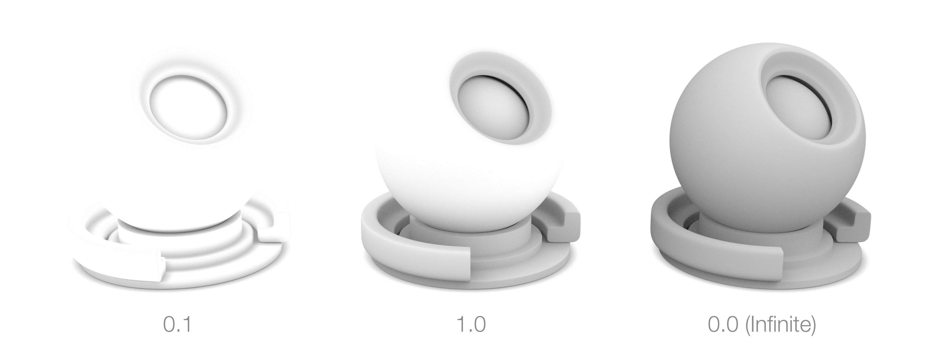
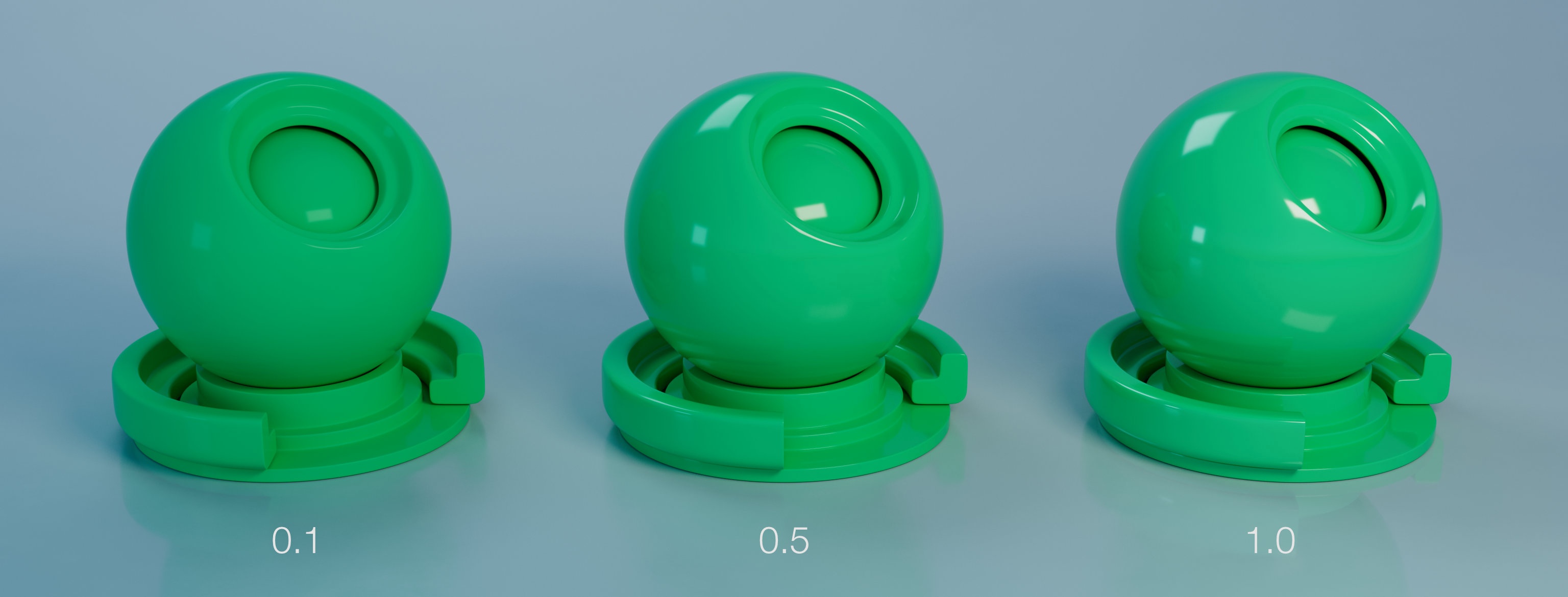
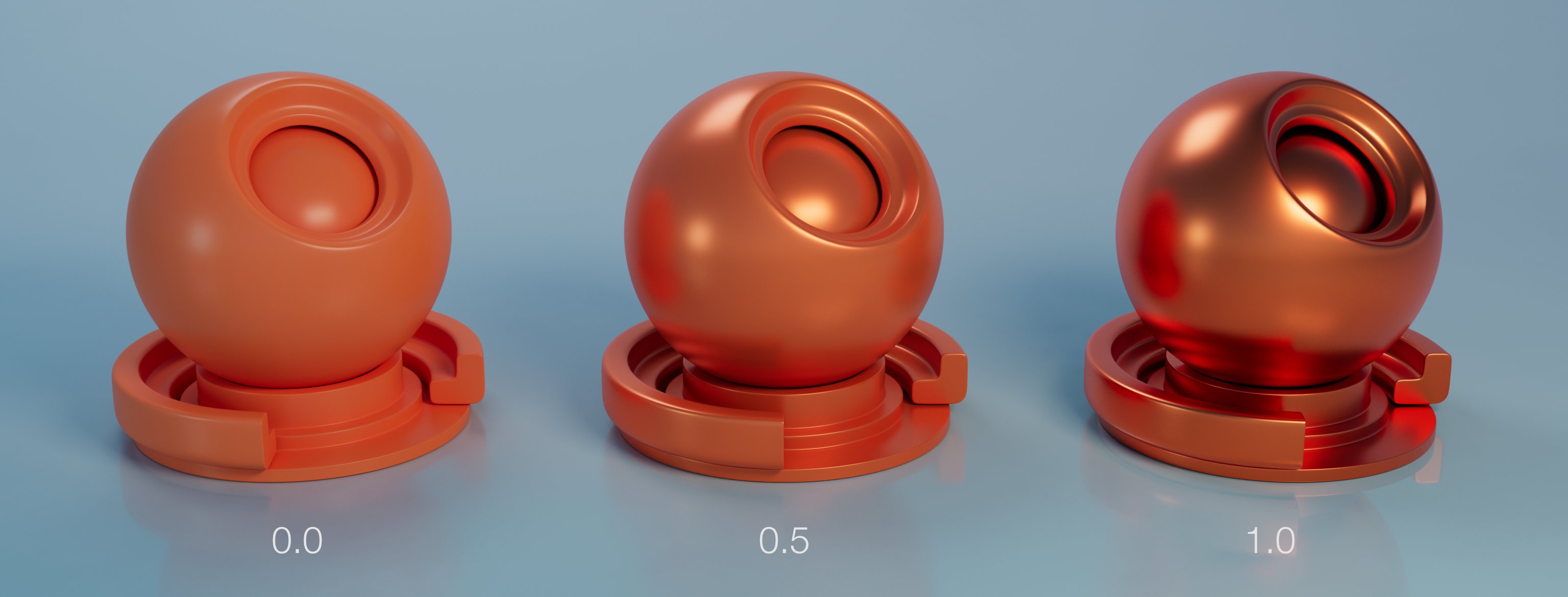
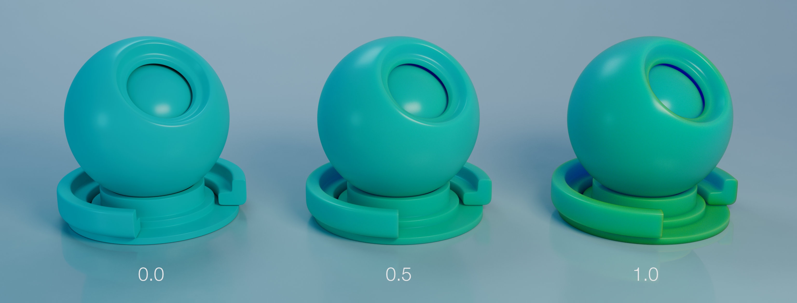
Thickness
The thickness of the coating layer. The thicker the layer the more it absorbs light and the less of the base layer is visible. A thickness of 0 disables the coating the coating.
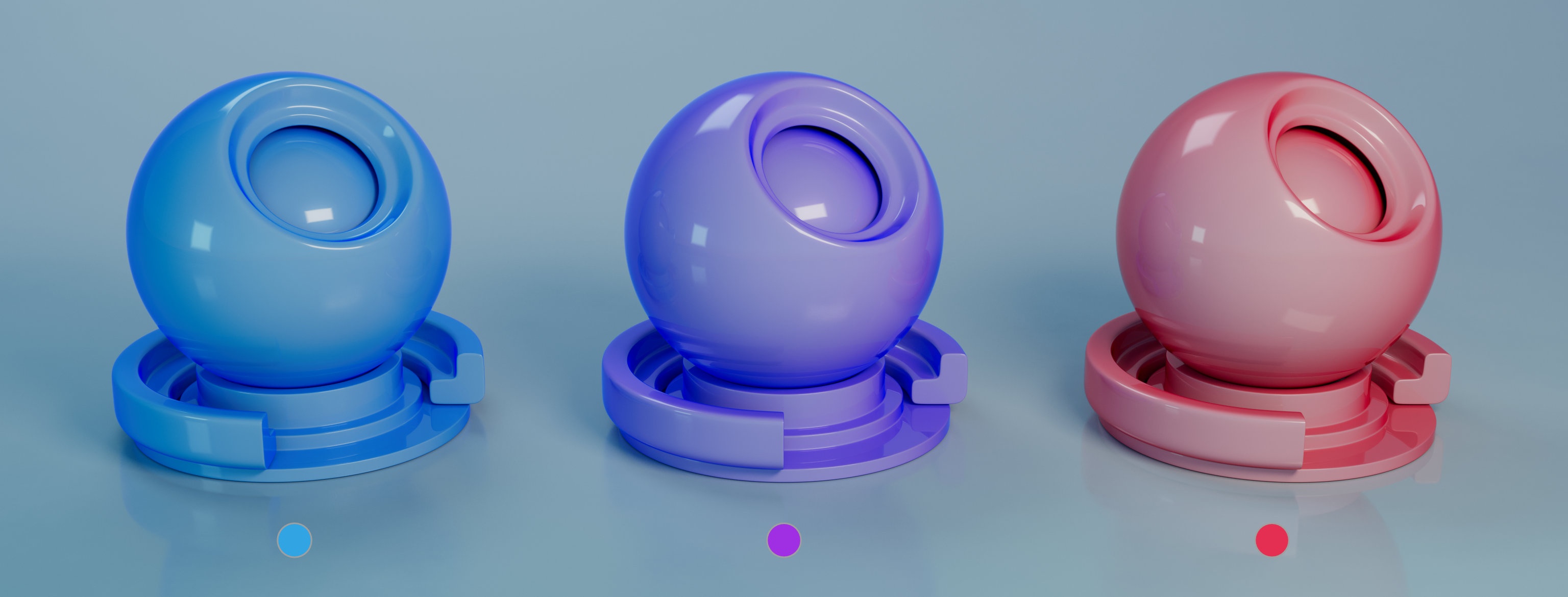
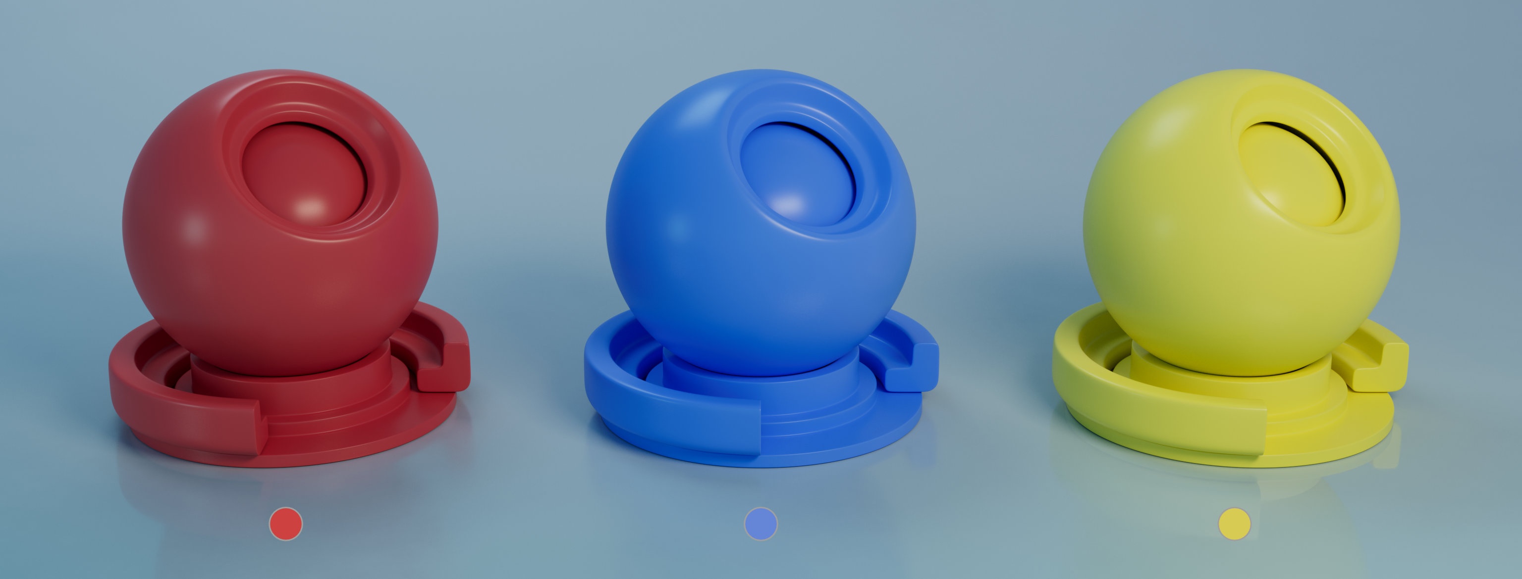
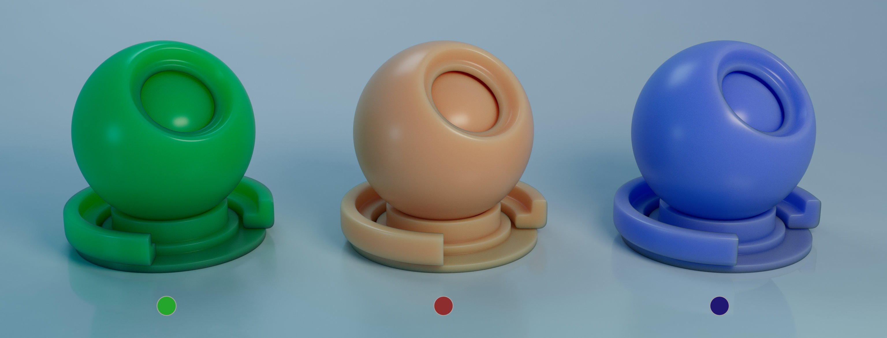
Color
The colouring producing by this coating layer. Colouring will be more prominent in thicker layers.
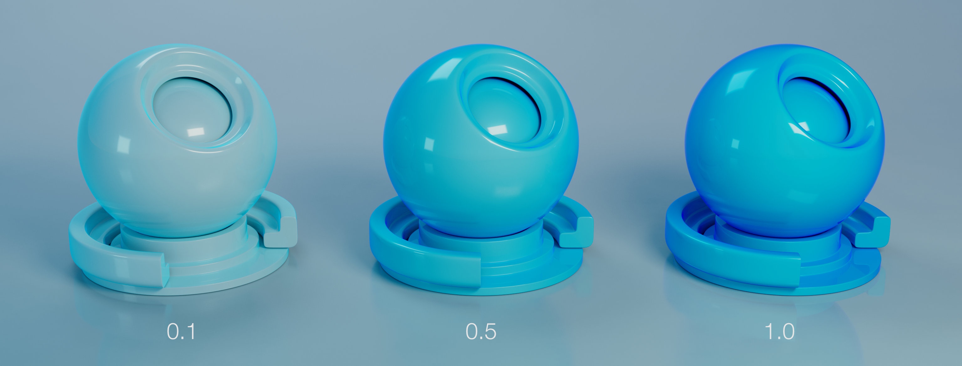
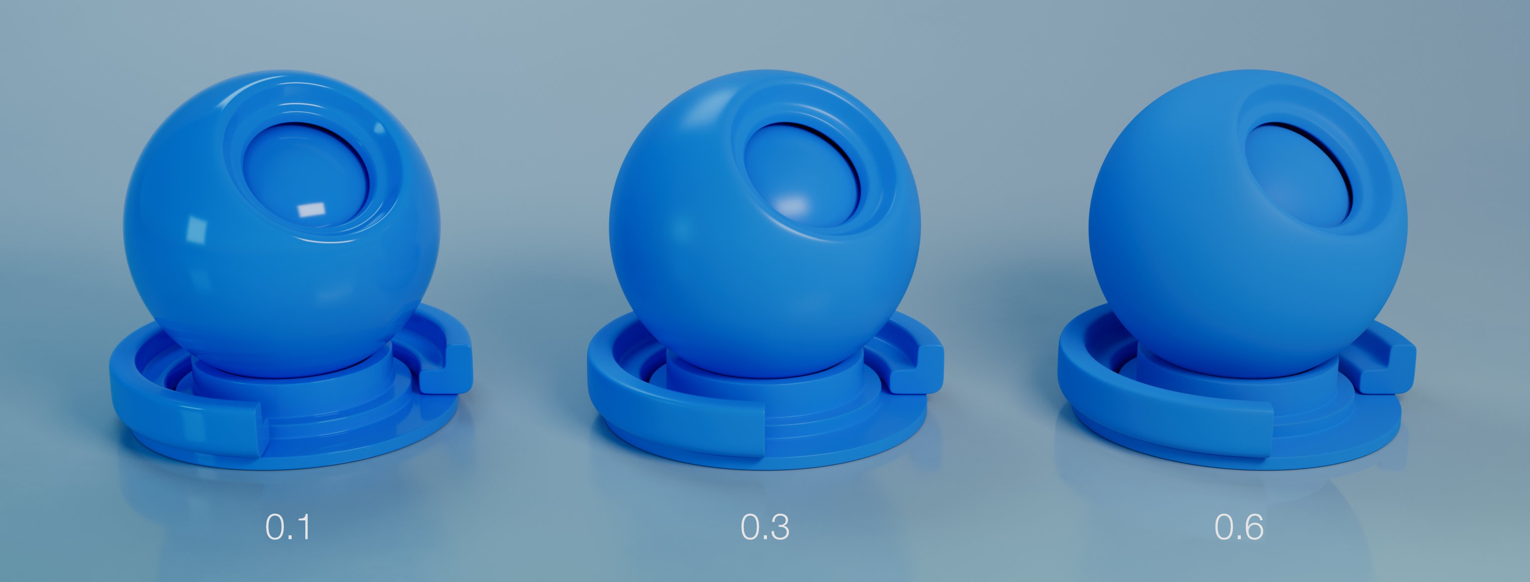
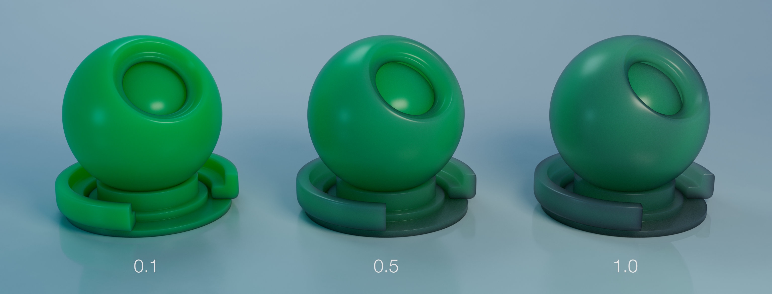
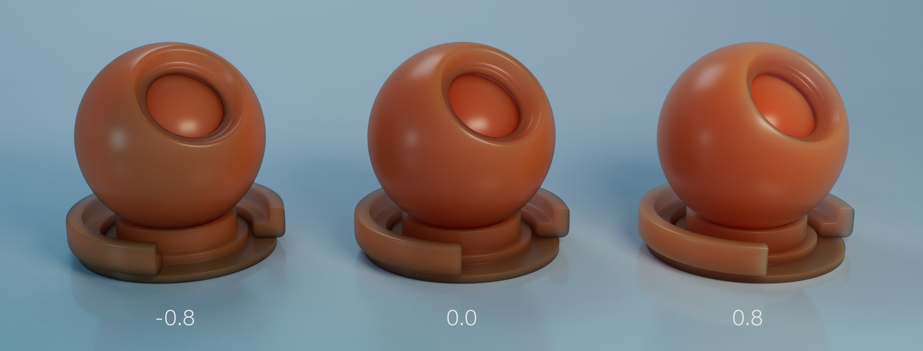
Roughness
Roughness of the coating layer.
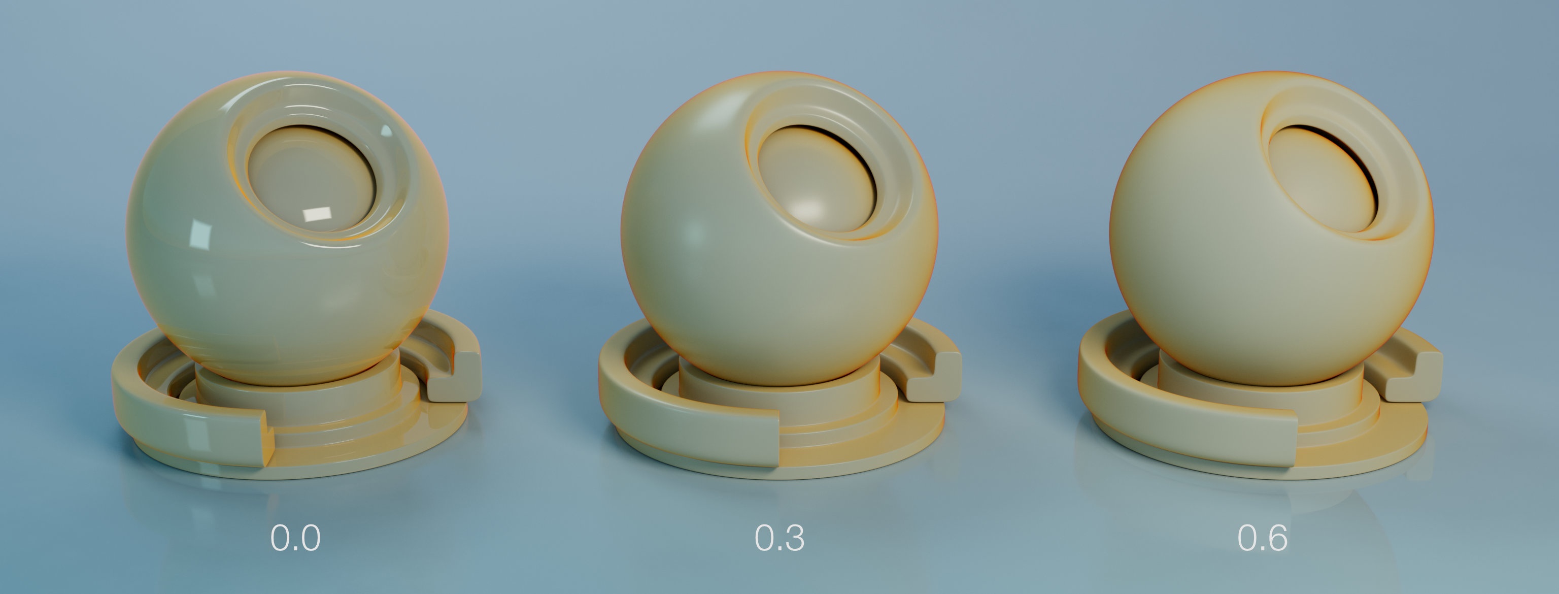
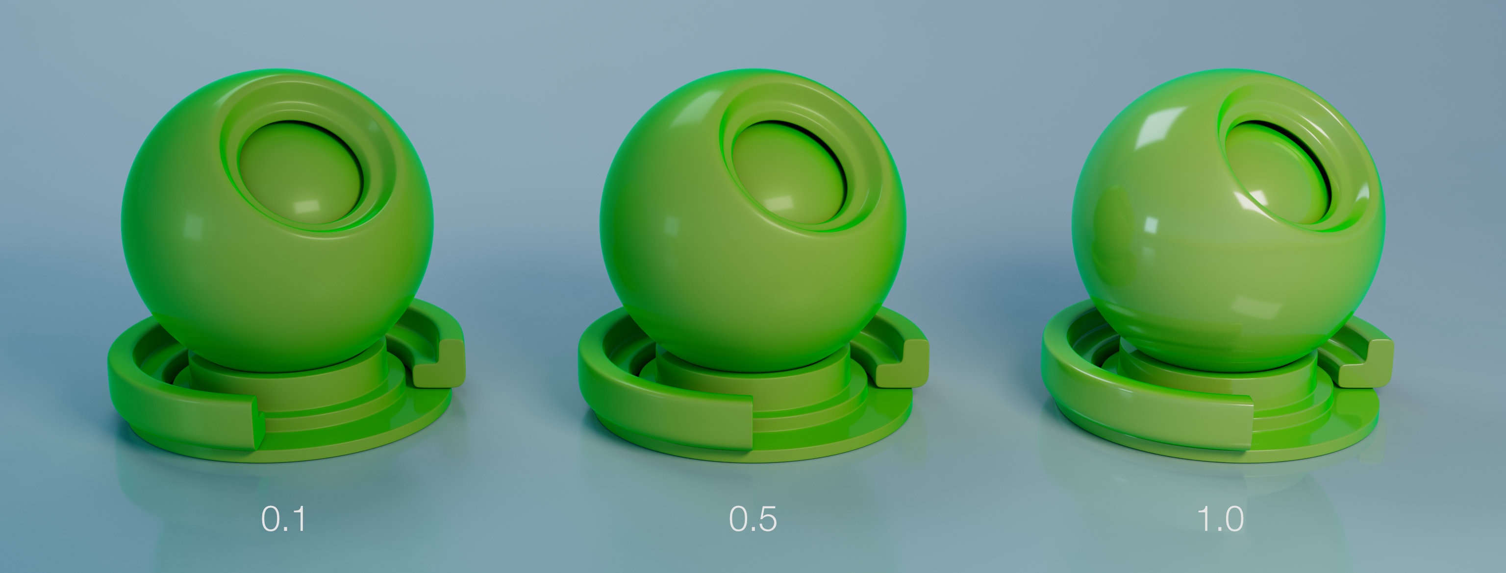
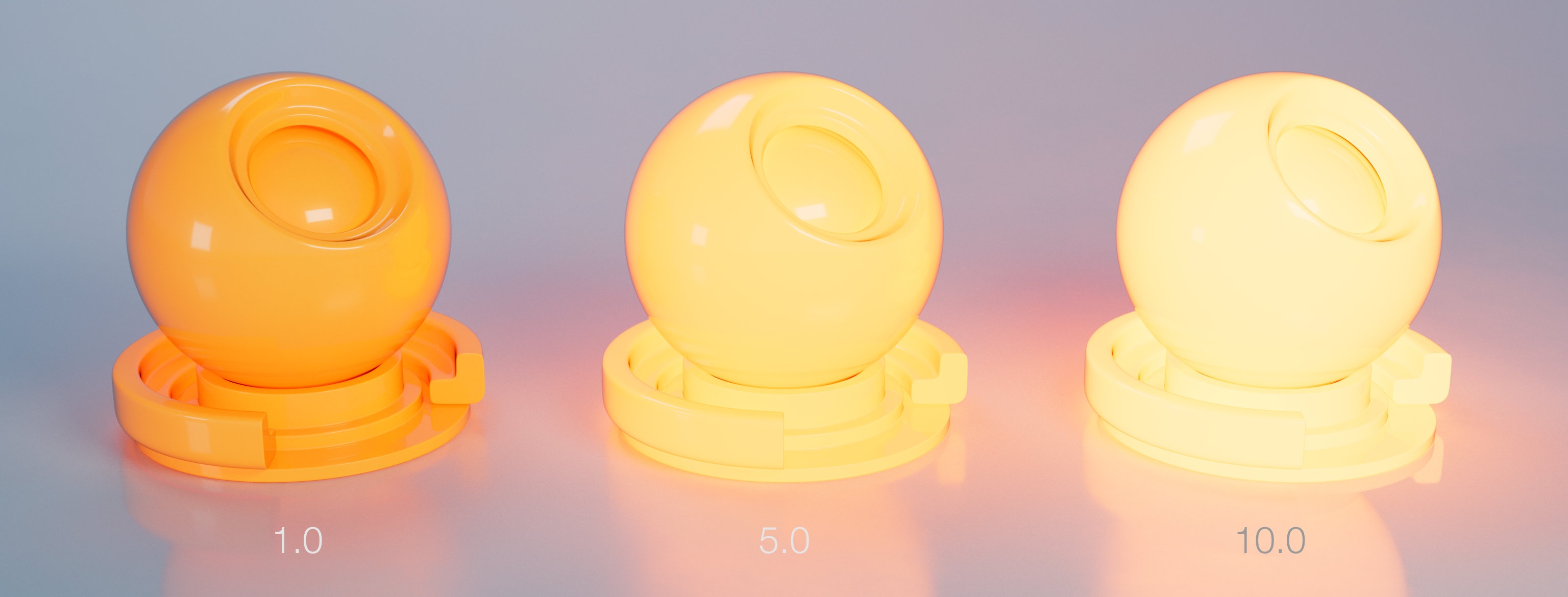
Specular Level
How "shiny" is the coating. A value of 1 means a very shiny coating.
Base |
|---|
Color
The colouring producing by this coating layer. Colouring will be more prominent in thicker layers.
Roughness
Roughness of the coating layer.
...
colour of the base layer.
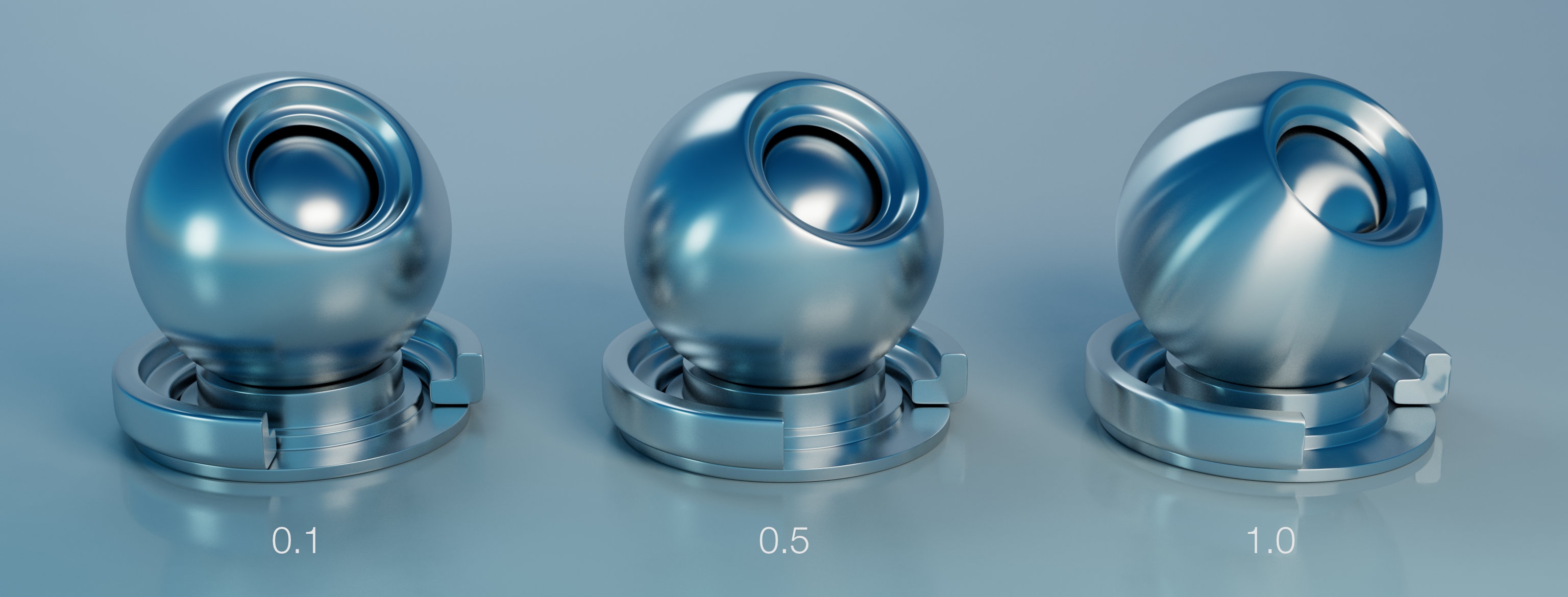
Roughness
The roughness of the base layer.
Specular Level
Controls the strength of specular reflections on the base layer.
Metallic
Reflect AOVs
Anisotropy
Anisotropy Direction
Opacity
Subsurface |
|---|
Weight
Color
Scale
Anisotropy
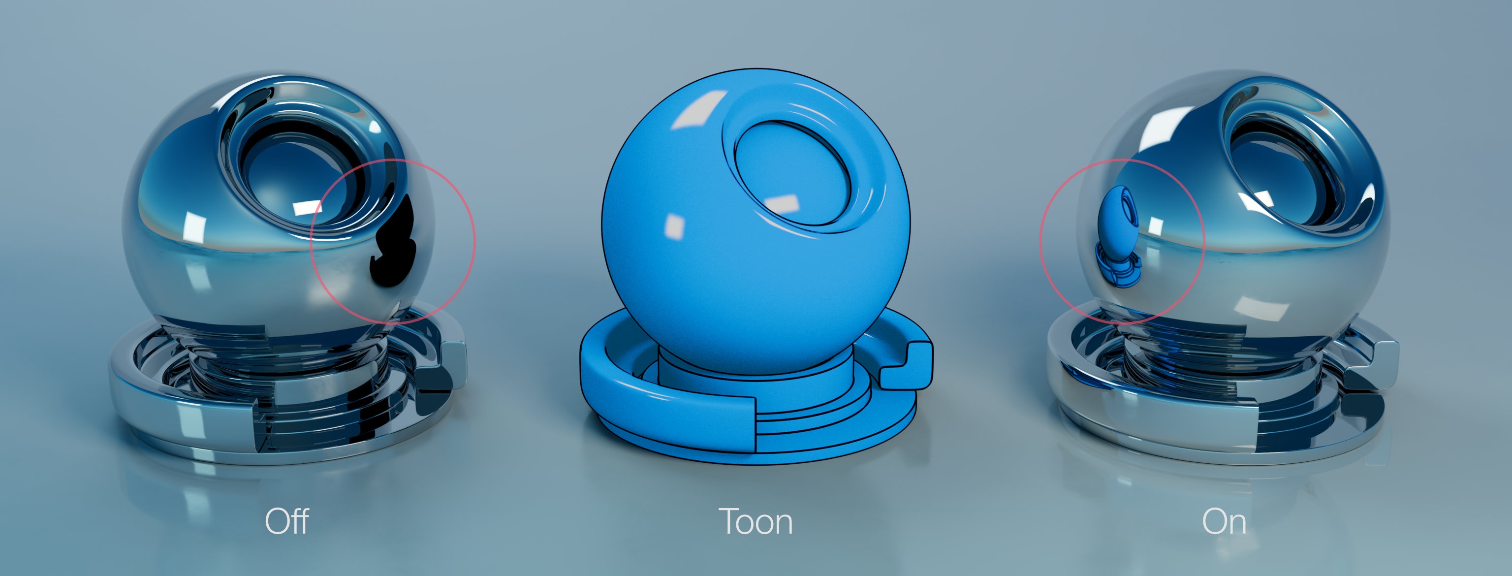
Merge Set
When two or more subsurface volumes overlap, their internal boundaries can create darker (or brighter) areas on the surface. Setting their Merge Set to an identical name disables those boundaries and their effect on the surface, effectively merging the volumes together.
Dominant Material
When two or more subsurface volumes overlap, a mix of their properties will normally be used inside their intersection. Checking this option for one of the materials will prevent this mixing and ensure it's used exclusively.
Double-Sided
Allows the SSS simulation to be entered and exited from the front or the back of a surface. When this option is disabled (the default), the simulation is entered only from the front and exited only from the back.
Refraction |
|---|
Color
![]()
Scattering
IOR
Roughness
Density
...
Anisotropy

Anisotropy Direction

...
Subsurface
Color

Scale

IOR

Incandescence |
|---|
...
Colour of the emitted light.

Intensity
Intensity of emitted light. Final colour is Colour * Intensity.
Bump / Normal / Displacement Map |
|---|
| Include Page | ||||
|---|---|---|---|---|
|
Geometry |
|---|
Occlusion Distance