Overview
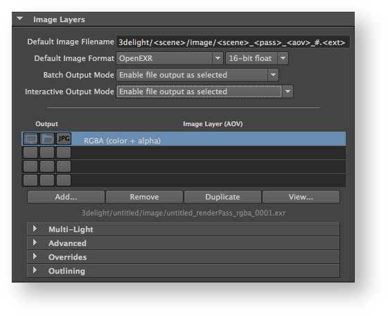
In the Displays Using the Image Layers group of attributes the user can specify what images (or Displays) will be rendered; each display specifies one or several layers of images to output simultaneously from the rendering process. Each can be set to output to a file or a screen window, use a specific Arbitrary Output Variable (AOV), or even contain a subset of the rendered scene. By default, there one display. However, it is possible to add several distinct displays that will all be rendered simultaneously (in a single render pass)be displayed on screen (in a window) or be saved in a file or both. By default, the Image Layers group of attributes is setup to output only one image layer: the RGBA components representing the main image, also commonly referred to as the Beauty. And it is setup to be displayed on screen and saved in a file.
It is possible to add any number of displayslayers, each set to output any AOV that are declared in the shaders.
 The Displays group
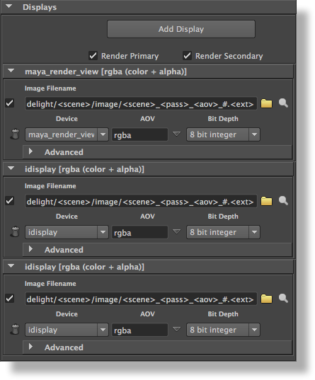
To add a display, either click on the Add Display button, or select Add Display in the contextual pop-up menu that appears when right-clicking almost everywhere in the Displays section. Each added display have its own panel. The pop-up menu also offers options to expand or collapse all display panels at once. To remove a display, click on its Remove Display button, which appears as a trashcan. To duplicate a display, right-click anywhere above the display to duplicate and select Duplicate Display menu option.
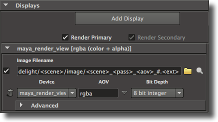
At the top of the Displays section are a few general controls, followed by a list of per-display panels. The general controls are:
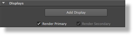
Add Display
Clicking this button will add a new display attribute group at the bottom of the displays panel.
Render Primary Display
Controls if the primary display is going to be rendered. The primary display is always the display at the top of the displays panel and this control is tied to the first display’s Render toggle. It can be useful to turn this option off when you need only need to render a secondary display or shadow maps. By default, this toggle is on.
Render Secondary Displays
Specifies if the other displays than the first one are rendered. This toggle will override the per-display Render toggle. This control is on by default.
Each display has its own panel showing the basic display parameters on two rows. The remaining display attributes are located in the Advanced section.
Group for a specific display
complementary information to the Beauty image, such as:
- Variables computed inside shaders, commonly called Arbitrary Output Variables (AOVs), such as depth values associated to the Beauty image, original color of surfaces (without the effect of the lighting), the specular and diffuse shading components of the Beauty image. Refer to AOV Selector for further details on supported AOVs and how to define custom ones.
- Contribution of individual or group of lights to the Beauty image.
- Any number of arbitrary masks derived from objects and/or materials.
Such layers can be useful for compositors to have many options while composing the final image and/or rapidly establishing the right light balance.
Layers can not only be generated for different AOVs, Lights and Masks, they can also:
- Have different camera angles. This is very useful for fast simultaneous multi-camera rendering (for 3D stereo for example).
- Contain a different subset of objects in the scene.
| Info |
|---|
All the layers are rendered simultaneously. Adding many layers do not generally increase rendering time significantly. This is different and not to be confused with the 3Delight for Maya functionality of Render Passes. Those are processed sequentially and can produce totally different output from one pass to another. |
| Warning |
|---|
Windows only: Writing to disk many Image Layers may result in a performance bottleneck on Windows file systems. This is not the case on more efficient file systems such as Linux (ext4) and MacOSX (hfs+). |
| Tip |
|---|
Multi-Layer EXRs: to write all Image Layers in the same EXR file, simply set the exact same Image Filename. In the screenshot below this would imply removing the
|
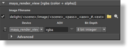
A display panel’s first row offers the following attributes:
A Render toggle
The check box on the left side of the image filename controls if the display will be rendered or not. Since the first display in the panel is considered the primary display, its Render toggle is tied to the Render Primary toggle. For other displays, their Render toggle is acknowledged only when Render Secondary is turned on.
An Image Filename
...
The Image Layers group
Global Options
Default Image Filename
Specifies the default file location for the image layers. By default, the location is based on the scene name, the render pass name and the AOV name. See File Path Expressions
for details on how it is possible to construct relative paths and
...
paths containing dynamically expanded tokens.
A Browse for Image File button
This button, drawn as a folder, brings up a file browser to specify an image filename.
A View Image button
This button, drawn as a magnifying glass, will open the display’s image file in a viewing application. See Section 3.17 [The Preferences Window], page 93 for details on how to specify which application should be launched.
The second row offers the following attributes:
A Remove Display button
This button, drawn as a trashcan, removes the display from the render pass.
...
This options specified the type of the display driver, which is where your rendered image will go. The following display drivers are available:
Default Image Format
Specifies the default file format for the image layers, including the pixel bit depth. The default is 16-bit float EXR files. Many formats are supported and each have specific options for bit depths. Refer to Image File Formats for more details.
Batch Output Mode
Each image layer have a file output toggle controlling wether it should be saved to file during rendering (this is explained below). Since these toggles may be manipulated frequently while working interactively and may be forgotten in a OFF position when sending the rendering to a render farm (using the Maya Batch command line), the Batch Output Mode controls wether these toggles should be ignored (overridden) when rendering in batch mode. This option is useful to make sure all image layers are saved when rendering using the Maya Batch command line, regardless of the status of the file output toggle. The options are:
Enable file output as selected | Indicates to output the image layers to file (in batch mode) only if their corresponding file output toggle are selected. This is the default, it follows the same behaviour as in interactive mode. |
Enable all file output and selected JPEG | Indicates to ignore (override) the file output toggles and request that all image layers be saved to file when in batch mode. With regard to the output of a JPEG file, only those that are selected will be output to file (meaning the Batch Output Mode have no overriding effect to the JPEG output toggle and those are output only if enabled, wether in batch or interactive mode). |
Interactive Output Mode
The Interactive Output Mode allows to globally control the behaviour of the file output toggles while working during an interactive session. The options are:
| Section | ||||||||||||||||
|---|---|---|---|---|---|---|---|---|---|---|---|---|---|---|---|---|
|
List of Layers (AOVs)
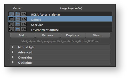
The second section of the Image Layers group is use to specify the list all the layers that will be generated during the rendering process (subject to the selection of any of the three output toggles in te list). By default, the list is populated with only one image layer, the RGBA ("Beauty") layer. When there are many layers, it is possible to re-order them in the list for organisational purpose (to visually group them). This is done through a middle-click and drag. It is a bit finicky to use though - you need to drop the layer while a line in between two layers is highlighted for the re-order to work. If you drop the layer while another layer is highlighted, nothing happens.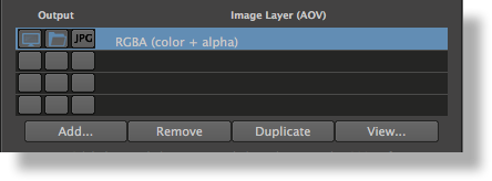
List of Layers (AOVs)
Each layer can be selected to be displayed on screen while rendering or be saved to file or both. They can be saved in the specified format and also simultaneously in JPEG (similar in concept to a digital camera that can save simultaneously a RAW and a JPEG image). These outputs (display on screen and save to file) for each layer is controlled using three toggles located left of the layer name in the list. If no output toggles are selected, the image layer with its AOV is inactive.
| Section | |||||||||||||||
|---|---|---|---|---|---|---|---|---|---|---|---|---|---|---|---|
|


If all three toggles are selected, the image layer will be outputted simultaneously in a screen window, on file (in the specified format) and as a jpeg.
Below the list of layers there are four buttons. Except for Add, their function applies to the selected layers in the list:
Add...
For adding layers. The AOV Selector will pop for enabling one or more AOVs. All the AOVs selected in the AOV Selector are presented in the list of layers.
Remove
Select one or more layers in the list and press Remove to remove. Note that the RGBA ("Beauty") layer can not be removed.
Duplicate
Select a layer in the list and press Duplicate to duplicate. You can then change some of the per layer attributes for any of the duplicated layer (otherwise you simply end up with exactly the same Layer/AOV without any difference). For example, you can have two Diffuse layers saved in different file format, or each with a different Pixel Filter or Display Subset (specified in the Advanced groups of attributes).
View...
Select a layer and press View to view it. This opens the Image Filename for that layer in a viewing application. Refer to The 3Delight Preferences for how to select which application should be launched.
Per Layer Attributes
When selecting a layer (only one) in the list of layers, its attributes are listed in collapsable groups below the Add/Remove/Duplicate/View buttons. These are per-layer attributes. The expanded file name for the selected layer is shown just above these collapsable groups.
 Groups of attributes for a specific Layer
| Collapsable Group | Description | ||
|---|---|---|---|
| Multi-Light | See Layers Multi-Light. | ||
| Multi-Mask | See 3Delight Multi-Mask. | ||
| Advanced | See Layers Advanced. | ||
| Overrides | This group is to override the following attributes for the selected layer: Image Filename Use to override the Default Image Filename. The options are "Default" to use (not override) the Default Image Filename and "Custom" to specify a custom filename for the selected layer. When default is selected, the complete expanded filename is listed just below (expanded from the token). File Format To override the Default Image Format. The options are "Default" to use (not override) the Default Image Format and "Custom" to specify a custom file format, including the pixel bit depth.
| ||
| Outlining | See Layers Outlining. |
| Display Name | Description |
|---|---|
| idisplay | The rendered image is sent to i-display |
| maya_render_view | The rendered image is displayed in Maya’s Render View. Note that this display should not be used when rendering to a RIB file since it only works for rendering launched in Maya by 3Delight for Maya. |
| tiff | The AOV is saved in TIFF format. |
| iff | The image/AOV is saved in IFF format. Note that only 8 bits RGB or RGBA images can be output by the IFF display driver. |
| exr | The rendered image/AOV is output in a file in "Open EXR" format. The Open EXR libraries, which are not included in the 3Delight package, must be installed. This display driver only works in 16-bits float or 32-bits float. |
| cineon | The rendered image is output in a file in Cineon format. It is recommended to set the Bit Depth 32 bit float. |
| zfile | The rendered AOV will be a depth map file. It is recommended to set the bit depth to 32 bit float. The AOV in this case should be set to ‘z’. |
| eps | The rendered image is output in a file in Encapsulated PostScript format. |
| bmp | The rendered image is output in a file in BMP format. |
| psd | The rendered image is output in a file in PSD format. |
| radiance | The rendered image is saved in Radiance format. This display driver only works in 32 bits float. |
| null | The rendered image is discarded. |
| shadowmap | The rendered image will be a depth map in TIFF format, suitable to be used as a shadow map. Bit Depth has to be set to 32 bit float and the AOV to 'z'. |
Texture | The rendered image will be a mipmap TIFF, suitable to be used as a texture map without the need of converting it with tdlmake. |
| dsm | The rendered image will be a "Deep Shadow Map". The deep shadow map display driver has several restrictions: the Bit Depth attribute should be set to 32 bit float and the AOV should be set to "rgba". The required Pixel Filter is ‘box’ and the required Filter Width is 1 x 1. |
| jpg | The rendered image is output in a file in JPEG format. |
| pic | The rendered image is output in a file in Softimage’s PIC format. |
| png | The rendered image is output in a file in PNG format. |
AOV
Indicates what variable will be output during this render. The most common values are ‘rgba’ or ‘rgb’ for RGBA and RGB outputs respectively, which are usually referred as "beauty passes". You can specify here any predefined output variable or arbitrary output variables that your shaders are using. Inline declarations of arbitrary output variables are allowed, meaning that it is permitted to preceded a variable name with its type to declare it and specify it for the display mode all at once. Clicking on the arrow button next to the AOV text field brings up a popup menu that lists available predefined output variables.
The AOVs are explained in the Display AOVs section.
Bit Depth
This option menu specifies how many bits to use per color component.
| Warning |
|---|
| Some display drivers have specific requirements as to what bit depths are supported. Refer to Display Device. |
The available bit depth values are:
| Option | Description |
|---|---|
| 8 bit integer | The image will use 8 bits integer values for each component, with values defined between 0 (black) and 255 (white). This corresponds to a quan- tization of 0, 255, 0, 255 for zero, one, min and max, respectively, and a dither value of 0.5. This is the default value. |
| 16 bit integer | The image will use 16 bits integer values for each component, with values defined between 0 (black) and 65535 (white). This corresponds to a quan- tization of 0, 65535, 0, 65535 for zero, one, min and max, respectively, and a dither value of 0.5. |
| 16 bit float | The image will use 16 bits float values for each color component. Cur- rently, only the ‘exr’ display driver supports this format. This corresponds to a quantization of 0, 0, 0, 0, and a dither value of 0 (identical to ‘32 bit float’); the display driver receives a pixel type specification through an option. |
| 32 bit float | The image will use 32 bits float values for each color component. This corresponds to a quantization of 0, 0, 0, 0, and a dither value of 0. |
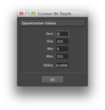
| Custom... | All images are rendered internally in 32-bits float format. Quantization is the process of assigning integer values to these floating-point values. Some usual preset values are available in the "Bit Depth" attribute. If they do not include the needed variation, it is possible to specify custom quantization values by selecting this menu entry. Upon selection, a dialog pops up, displaying the current bit depth settings:
The Custom Bit Depth Dialog It allows specification of values for zero, one, min, max and dither amplitude. zero is the black point, while one is the white point. These two values can be different from the min and max values if you need to have under-exposed or over-exposed values. An example set of values for 12 bits output with standard dithering would be: 0, 4095, 0, 4095, 0.5 An example set of values for 16 bits output with a white point at 4K that prevents over-exposed pixels from being clamped to the white value, would be: 0, 4095, 0, 65535, 0.5 |
| Other Custom entries | The option menu will also list all custom bit depths defined for all of the current render pass’ displays. |
Advanced Options
...
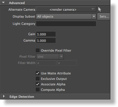
The Advanced group, which is collapsed by default, offers the following attributes:
Alternate Camera
This attribute can be used to specify a different camera than the Render Camera (specified in the Scene Elements group) to be used for this display. This allows simultaneous multi-camera angle or stereoscopic rendering. For best performance, it is recommended to keep as many displays as possible set to <render camera>. For instance, when working with a stereoscopic project that has a "left eye" camera and a "right eye" camera, it is preferable to set the Scene Elements' Render Camera to the "left eye" camera, and alter the value of the display's Alternate Camera only for the ones needed the "right eye" camera (instead of having all displays overriding the render camera with either the "left eye" or the "right eye" camera). By default, the display will use the Render Camera.
Display Subset
This attribute is used to select one or several Maya sets that is used to narrow down what objects will appear in the display. Set selection is made using the 3Delight Set Selector window which is invoked by clicking on the Sets... button. The "Display Subset" option menu specify how the selected sets will be interpreted and has the following values available:
| Option | Description |
|---|---|
| All Objects | All visible objects will appear in the display, disregarding any sets selec- tion made in the 3Delight Set Selector. This is the default. |
| Objects in selected sets | Only visible objects in the selected Maya sets will appear in the display. |
| Objects not in selected sets | Only visible objects that are not in the selected Maya sets will appear in the display. Put differently, all objects in the selected sets will be excluded from the display. |
Light Category
This attribute specifies a light category (see Category); only the lights of this category will appear in the display. This option requires setting the Render Engine attribute to Path Tracer (see Render Engine).
Gain
Specifies the gain. Each rendered pixel’s color will be multiplied by this value. ‘Gamma’ Specifies the gamma. Each rendered pixel’s color, once affected by "Gain", goes through a power function whose exponent is 1 / "Gamma".
Override Pixel Filter
Each display can have its own filter and filter width values. This toggle is off by default, in which case the display will use the values specified in the Quality section of the render pass. When this toggle is on, these values are overridden with the values specified in the following two attributes: ‘Pixel Filter’ ‘Filter Width’ These two attributes are identical to the "Pixel Filter" and "Pixel Filter Width" in Rendering Quality.
Use Matte Attribute
When this toggle is off, and if the display’s output variable is set to an arbitrary output variable, any matte attribute set on objects will be ignored. This toggle is on by default. Refer to the matte attribute here Visibility.
Exclusive Output
When this toggle is off, and if the display’s output variable is set to an arbitrary output variable, objects that do not output that variable will be black. Turning this option on will make these objects transparent. This toggle is off by default.
Associate Alpha
When this toggle is off, the color of a pixel is divided by the alpha to produce an image with an unassociated alpha channel. By default, this toggle is on.
Compute Alpha
When this attribute is on and the display’s "Output Variable" is an AOV, an alpha channel is added to the AOV. It is computed based on the existence of the output variable for a given object. This toggle is off by default. Usually, when this toggle is on, it is recommended to turn off Associate Alpha.
Edge Detection Options
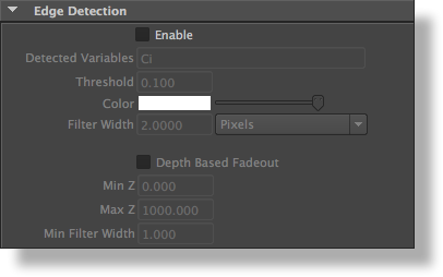
The Edge Detection subgroup
3Delight can perform outlining on any variable. This can be useful, for example, when doing toon rendering or illustration. An example scene can be found in ‘$DELIGHT/example/maya/outlines’. It is also possible to render shaded wireframes on polygon meshes; see [Polygons Wireframe], page 27.
Enable
This attribute enables edge detection for this particular display. it is set to off by default.
Detected Variables
This attribute specifies on what variables the edge detection (outlining) will run. Several variables can be specified, separated by a coma. For example, setting this attribute to ‘N,z,Oi’ will run edge detection on normals, depth and object contours. By default, this attribute is set to ‘Ci’, which is the color of the light reflected by an object.
Threshold
This attribute controls the sensitivity of the edge detection. The higher the threshold the more sensitive the edge detection is. For example, when detecting variations on ‘z’ (depth), a value of ‘0.1’ means that if there is a gap of ‘0.1’ between two surfaces (in the z direction) then an edge will be generated. This attribute is set to ‘0.1’ by default.
Color
This attribute defines the color of the generated outline. It is set to white by default.
Filter Width
This attribute defines the width of the generated outline. It is set to ‘0.2’ by default. Values between ‘0’ and ‘1’ are allowed, producing very fine outlines. In this case it is recommended to raise the "Pixel Samples" attribute (see [Pixel Samples], page 49) in order to avoid aliasing of the outlines.
Next to this attribute, there is an option menu to determine how this width should be interpreted. The possible values are:
| Pixels | The filter width is a number of pixels. |
| % of Frame Width | The filter width is taken as a percentage of the image resolution in X. |
Depth Based Fadeout
This attribute enables the edge thickness fadeout with depth. It is off by default.
Min Z
Max Z
These two attributes specify the depth range on which the fadeout will be performed. By default, "Min Z" is set to ‘0.0’ and ‘Max Z’ is set to ‘1000.0’.
Min Filter Width
...