Area Light and Mesh Light are both light sources emitting light from a geometric shape. They both use the same material. The only difference is that an Area Light offers a selection of pre-defined geometric shapes and the Mesh Llight offers no predefined choices but requires the selection of any geometric object to be used for light emission.
Creating an Area Light
An area light source can be created in the GafferThree's Object table by right-clicking in the light list section and selecting Add → Area Light, or by pressing the A key. It will be shown in the Viewer with the shape as selected in the Objects tab. For planar shapes, a line perpendicular to the plane is drawn to indicate the light's forward direction.
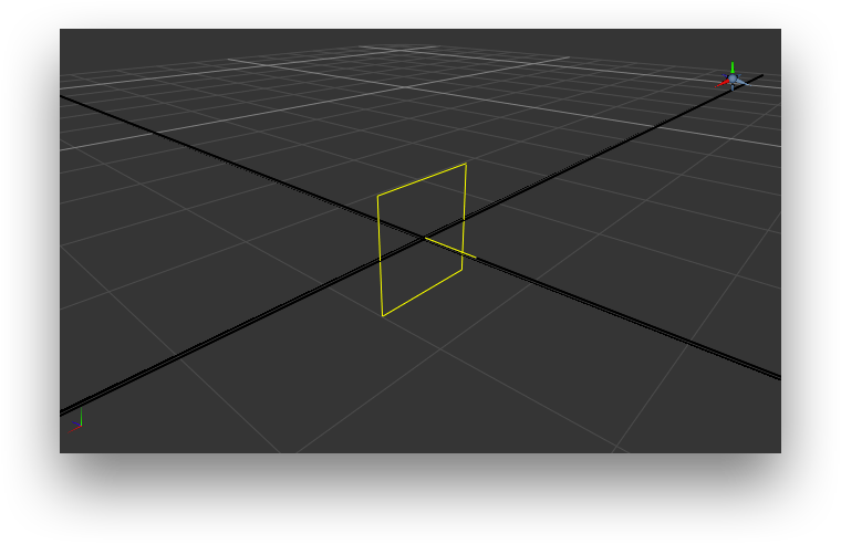
An area light in the Gaffer Object Table and in the Viewer.
Creating a Mesh Light
To create a mesh light source, right-click in the GafferThree's Object table and select Add → Mesh Light, or press the T key. The mesh light has no representation in the Viewer until an object or a group is set as its Source Mesh. Once this is configured, the mesh light appears as the source mesh in the Viewer. If the source mesh is set to a group, the mesh light's scene graph location will need to be expanded in order to be displayed in the Viewer.

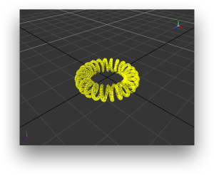
A mesh light in the Gaffer Object Table and in the Viewer.
Selecting and Positioning the Shape of the Light
The object tab allows specifying the shape of the light source using the Shape parameter (for the area light) or Source Mesh (for the mesh light).
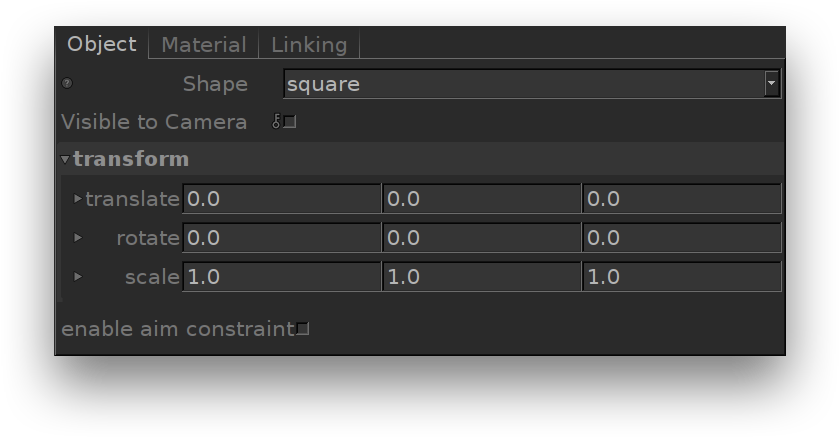
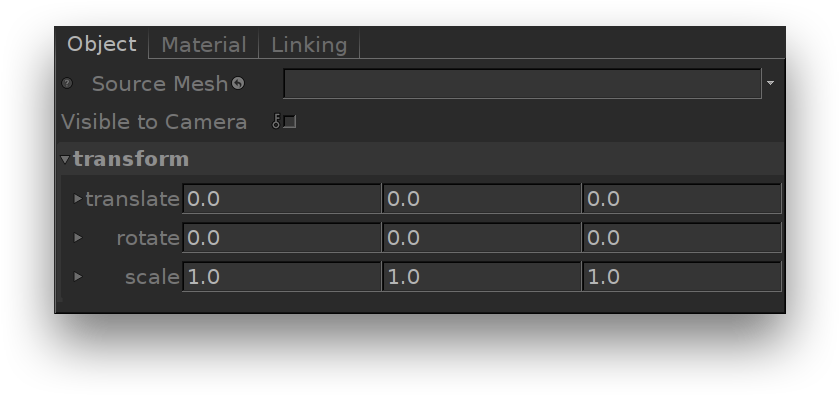
The Object tab of an area light (left) and of a mesh light (right).
Shaping the Mesh Light
The Source Mesh parameter allows using any geometric object or group as the light shape.
The object scene graph location can be specified by a few different means: Note that the assigned object should have its scene graph location defined by node placed upstream in the node graph.
Once a source mesh is specified, a copy of that source object or group is maintained under the mesh light. The original source mesh, which does not emit light, remains in the scene and will be rendered. If this is not desired, a Prune node can be added to the recipe downstream of the GafferThree to exclude the object that does not emit light.
Positioning the Light
The light's transform can be edited in the Object tab. It can also be edited interactively in the Viewer. The object tab also presents the enable aim constraint option which, if turned on, will display the standard GafferThree parameters for aim constraint.
Adjusting the light shape visibility
The shape of the light source can be made Visible to Camera in the Object tab.
Controlling the Light from an Area Light or a Mesh Light
The Material tab serves to control several light parameters. The effect of these are explained and illustrated in the next sections.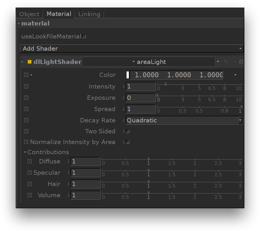
The Material tab of a light source using the area light shader.
Color, Intensity and Exposure can be adjusted using their respective gadget in the GafferThree's object table. Exposure and Intensity can also be adjusted through 3Delight Display's Mixer for lights that have their own Mutli-Light image output.
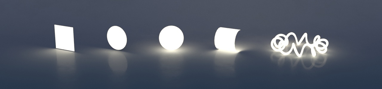
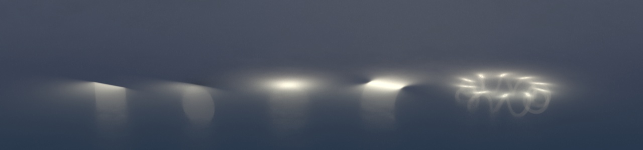
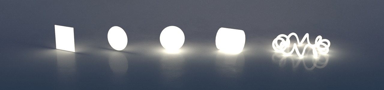
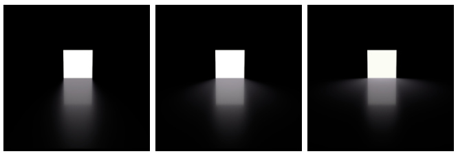
Shape Allows the selection of one of the default shapes (square, sphere, disk and cylinder), or specify a custom geometry (the mesh of a torus shaped filament in this example). Here is an illustration of these shapes over a slightly reflective floor: Visible to Camera Makes the light source visible to the camera (a.k.a primary rays in technical term). By default, Visible to Camera is off as shown below. In the image illustrating the Shape (above), Visible to Camera is on. Two Sided When enabled, the light will illuminate from both sides. Comparing to the image in the first illustration above (for the Shape whereas Two Sided is off) and this one below (Two Sided on), we can see increased illumination underneath the sphere, cylinder and mesh lights. This is because for such closed or partially closed objects, illumination from the interior (opposite side) of the light source does add to the total illumination. This happens because area lights shapes are created in such a way to not cast shadows (even when you make them visible to the camera). It should be noted also that since two-sided area lights emit light in both directions, they will illuminate anything enclosed within. Prelit The effect of this light will be considered as already baked into objects with the "Prelit" compositing mode. This is used to implement Prelit Materials as described in Prelit materials: light transport for live-action elements in production rendering. Light Spread Specifies the spread of the light. A spread of 1 is to natural "cosine" spread. Lower spreads will produce a more focused light. From left to right: 0.2, 0.5 and 1.0 (default). Normalize Intensity by Area This will divide the total intensity of the light by its area. The net effect of this is that no matter the size of your light, the intensity will remain the same. This non-physical behaviour can be handy when adjusting shadows from area light: penumbra (shadow softness) adjustment can easily be done by changing the size of the area light while not affecting its overall intensity. Color Defines the light color. Intensity Species the light intensity. Exposure This is an additional control over the standard light intensity. Exposure is in many cases a preferred control due to its likeness to photography. Final light intensity is thus computed by: Decay Rate Specify the rate at which the light intensity decreases in function of the distance to the light source. The available values are: It is sometimes useful to have a fine and direct control on how the light intensity affects various shading components. The following controls allows for that: Diffuse Contribution Specifies a multiplier for the light contribution to diffuse shading. Specular Contribution Specifies a multiplier for the light contribution to specular shading. Hair Contribution Specifies a multiplier for the light contribution to hair shading. Volume Contribution Specifies a multiplier for the light contribution to volumetric effects in atmosphere and OpenVDB volumes.Shaping the Light
Light Intensity and Color Controls
I = intensity * pow(2, exposure)No Decay
Light intensity remains constant with respect to distance. Linear
Light intensity decreases linearly with distance. Quadratic
Light intensity decreases proportionally to the square of the distance. This is the physically correct behaviour. Cubic
Light intensity decreases proportionally to the cube of the distance. Fine Tuning the Light Contribution to the Shading Components