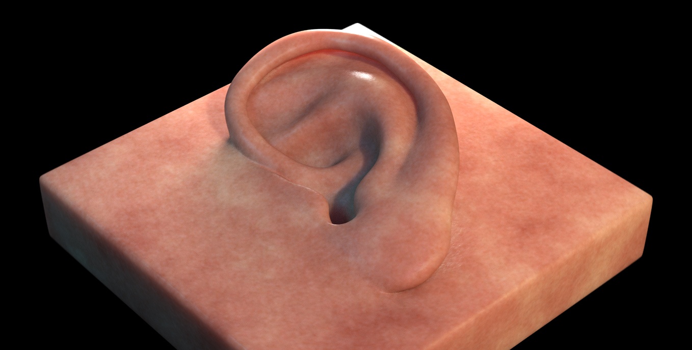
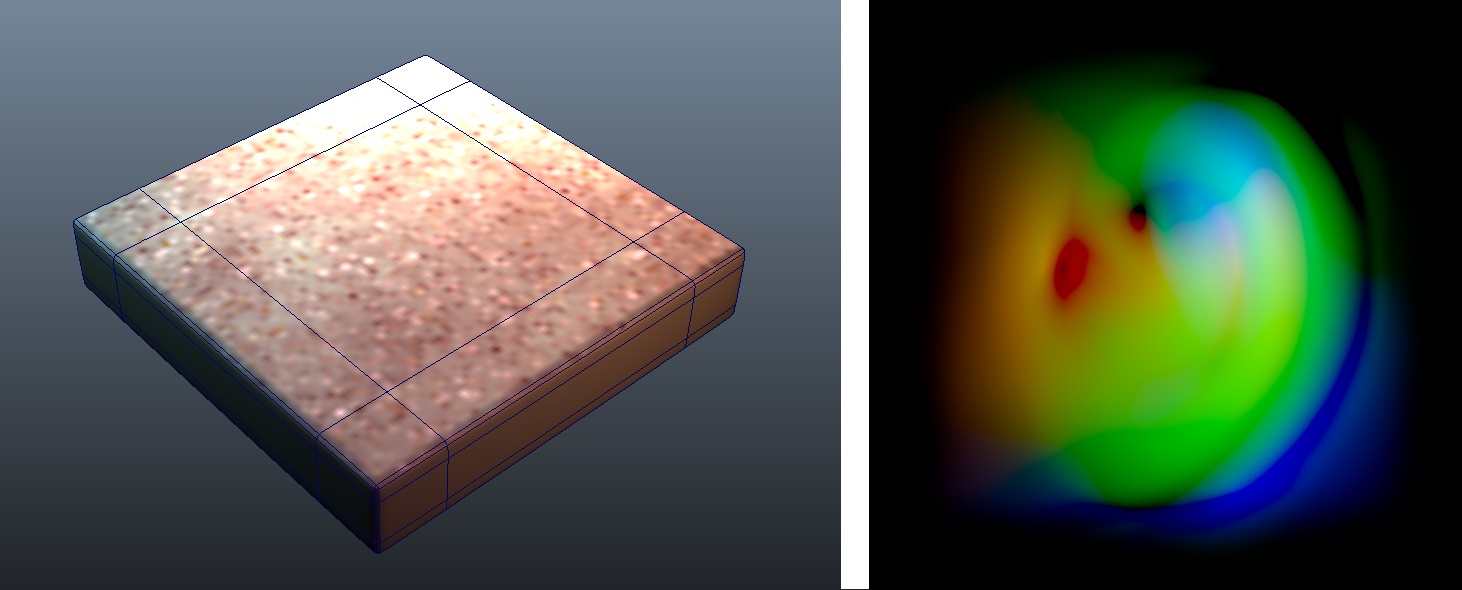
A simple vector displacement test. You can download the Maya scene here and the ear vector displacements map here.
This tutorial explains how to apply displacements in 3Delight for Maya. Both scalar and vector displacements are supported. Here is a model of an ear sculpted using vector displacements.
The usual way of rendering displacements in Maya is through the displacementNode. All parameters of the displacementNode shader are supported but some parameters have an extended meaning in 3Delight for Maya. All necessary details are explained below including all the relevant options for generating displacement maps from Autodesk Mudbox and Pixologic ZBrush.

displacementNode UI
Scalar Displacements
For scalar displacements, all parameters are recognised but one: Vector Displacement. It is not used for obvious reason: the displacement vector is implicitly the surface normal. Despite the misleading names, both Vector Encoding and Vector Space are supported in the case of scalar displacements.
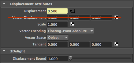
For scalar displacements, the Vector Displacement parameter is not used.
Vector Space
This parameter, which also applies to scalar displacements, defines in which 3D space the displacement is defined. The available options are:
Object Space | The displacement magnitude is expressed in the same space as the model. This means that if the object is scaled by some value, the displacement will follow the same scaling. |
World Space | The displacement magnitude is expressed in the world space. This means that displacement magnitude is independent of object scaling. A displacement value of 1.0 with a unit scale corresponds to a magnitude of 1 Maya unit. |
Tangent Space | The displacement takes place in a local coordinate system defined by the tangents on the surface. This mode is useful for vector displacement. |
Vector Encoding
This parameter, which also applies to scalar displacements, defines in which range the displacement is defined. The available options are:
Floating Point Absolute | The displacement range is between 0 and 1.0*Scale. The displacement will push the surface out. |
Signed Encoding | The displacement range is between -0.5*Scale and 0.5*Scale . The displacement will push the surface in and out. |
Vector Displacement Maps
Connecting a texture (or a procedural texture) into the Vector Displacement plug enables vector displacements. In this mode, the Displacement plug is ignored.

Displacement plug is ignored when Vector Displacement is connected.
By default, Maya will connect your File Node output to the Displacement plug of your displacement shader. This is suitable for scalar displacements, not for vector displacements. Make sure to connect the map (or network) to the proper Vector Displacement plug.
Here is an example of a network setup to use vector displacement map:
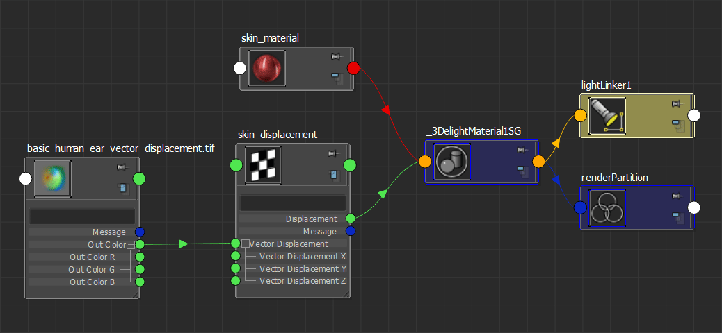
Displacement network to use a vector displacement map (used to render the "ear" scene).
When using vector displacements, check if your map was created in World/Object Space or Tangent Space and set the Vector Space parameter accordingly.
Adjusting the Displacement Bound
As explained in Displacement Technology, 3Delight needs bounds for the displacements to render properly. 3Delight for Maya guesses the correct displacement bound using the parameters in the displacement shader so in most cases the Displacement Bound is better left untouched. In some cases, however, it is necessary to adjust the bound to avoid artifacts or to optimize render times.
One instance in which the adjustment is necessary is when using floating-point displacement maps (or shading networks) that produce magnitudes larger than 1.0. In this case, the Displacement Bound should be set to the maximum value in the texture map or network. Usually renders which exceed the displacement bound will produce the following 3Delight error :
3DL R2001 object 'name' (displacement 'shader', surface 'shader') exceeded its displacement bound by 25%
A displacement bounds is be specified for the object but is not big enough. This could cut off displaced
parts of the object. Maybe the bounds should be enlarged.
The following render shows the kind of artifacts produced by insufficient displacement bounds:
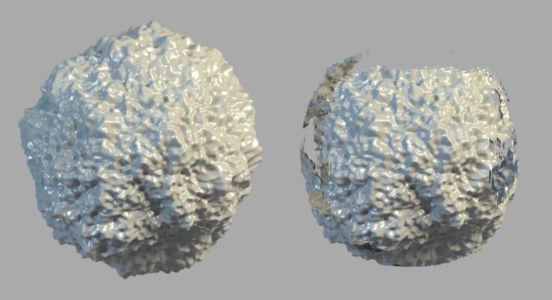
Correct Displacement Bounds (left) — Insufficient Displacement Bounds (right)
Another instance in which the Displacement Bound should be changed is when the range of the displacement map (or shading network) is much lower than one, in this case the bound should be lowered to reflect the actual range of the displacement map or network. Note this case won't produce artifacts, it is a simple optimization step. When 3Delight detects displacement bounds that are too large, the following warning will be produced:
3DL R2093 object 'name' (displacement 'shader', surface 'shader') used only 25% of its displacement bound
The displacement bound specified for the object is much larger than needed. Performance could be increased by reducing it.
Displacement Technology
3Delight supports two different displacement methods:
- Pixel level displacement. Geometry is tessellated on-the-fly and adaptively to meet highest quality criteria. This is the default.
- Vertex level displacement. Geometry is pre-tessellated to a given amount of subdivision prior to running the displacement shader. Vertex level displacement is enabled in the displacementNode inside the 3Delight section as show in the screen shot below.
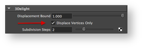 Enabling Vertex Displacement
Both approaches have their pros and cons as shown in the table below.
| Pixel Level Displacement | Vertex Level Displacement | |
|---|---|---|
Startup time | Fast startup time because no pre-processing is required. | Potentially slower startup time because of pre-tessellation requirement. This depends on the number of Subdivision Steps. The higher the steps the slower is the pre-processing time. |
Overall Render Time | Slower render times. | Usually faster render times. |
Memory Usage | Lower memory usage thanks to a smart caching system. This is not always true though: in this case, 3Delight needs to keep original geometry in memory and this could be expensive in case of subdivision surfaces. | Potentially higher memory usage depending on the Subdivision Steps. Although in the case of subdivision surfaces, this metod might use less memory overall because final tessellated and displaced geometry is stored as a polygonal mesh (more compact than the subdivision mesh counterpart). |
Quality | Provides very high quality displacement but might be subject to cracking, especially for vector displacement and large displacements. | Displacement quality depends on the Subdivision Steps. Note that 3Delight will use bump mapping on the final geometry faces to achieve a fine grained look. So even with low Subdivision Steps, high frequency details are preserved by varying the normal over the surface. |
Using Mudbox Displacements
3Delight for Maya can render Mudbox displacements (both vector and scalar) using the standard displacementNode shader. The following table explains how to export both scalar and vector displacement maps.
Scalar Displacement Export
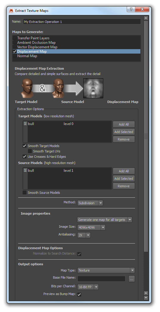
For scalar displacements:
- Select the Displacement Map option at the top.
- Make sure that Smooth Target UVs option is OFF.
Vector Displacement Export
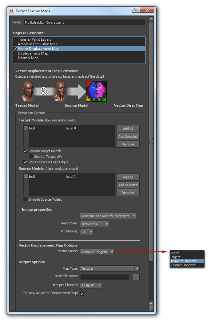
For vector displacement:
- Select Vector Displacement at the top of the panel.
- Make sure that Smooth Target UVs option is OFF.
- Regarding Vector Space:
- Non-deforming models with animated transformations, Object space is recommended.
- Completely static non-deforming models can use World space (but Object space will do just fine).
- For deforming models, Absolute Tangent is needed.
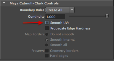
Disable Smooth UVs.
Using ZBrush Displacement Maps - Docs Work in Progress
In ZBrush you can export displacement maps via:
- Tool → Displacement
- Tool → Vector Displacement
- Zplugin → Multi Map Exporter (which allows to export other types of maps in one go).
There are two kind of displacement output:
- (Scalar) Displacement: this displaces the surface along the normal direction by a scalar value (a single float), either pushing the surface up, or down or both. In scalar displacement the direction cannot vary while displacing the surface.
- Vector Displacement: here the surface is displaced through a vector, the encoding allows for multi-directional displacement, so the surface is pushed up/down/both in a direction that may vary while displacing.
In both cases the workflow is the same:
- go the lowest subdivision level of your mesh
- export your displacement map
- export your base mesh model as an OBJ file (or use GoZ).
The relevant sections for displacement maps are evidenced screenshot:

(Scalar) Displacement and Vector Displacement map creation options
| Option | Displacement Type | Description |
|---|---|---|
| Adaptive | Scalar | ON (this produces higher quality maps) |
| DpSubPix | Scalar | This further subdivides the geometry, in memory, for higher quality displacement map creation. Each increment above 0 will quadruple the number of polygons. A value of 1 or 2 makes sense if you of not have a very detailed mesh at a high SubDiv level. |
| SmoothUV / vdSUV | Scalar & Vector | ON (smooths the UVs are before the map is generated) |
| Mid | Scalar | Only for 16 bit maps. This is the displacement mid value and depends wether you want the displacement to push the surface in&out / in / out (when set to 0.5: the displacement will push the surface in and out). |
| FlipV | Scalar | ON (flips the UV's V direction, this is necessary for 3Delight) |
| Scale | Scalar | The unit scale of the map; higher values will exaggerate the displacement. For 32 bit maps the value should normally be 1. Note that this relates to the units used in Maya (by default "cm"). Check what are the units used in your Brush project. |
| 3Channels | Scalar | OFF (this outputs 1 channel only, this is enough for 3Delight) |
| 32Bit / vd 32bit | When ON this export a 32 bit float map in TIF or EXR. When OFF the map will be 16 bit (which is usually enough in terms of quality but requires you to set the 16bit scale value, see below). NOTE that ZBrush does not export 8bit displacement maps. | |
| vdTangent | Vector | Sets how the vector displacement map is computed – whether it’s based on the normal of the polygons or based on the world axis. With it turned on, ZBrush will create a Tangent map. Turned off will produce a World map. Because animated objects are in motion relative to the world coordinate system, Tangent mode must be used any time your model will be animated. World mode is suitable for static (non-animated) renders. |
| vdDNormals | Vector | Smooths the low resolution model’s surface normals and results in a smoother map. |
What Bit Depth to Use ?
This is a very common question and the answer depends on both the type of the map used (scalar or vector) and the type of the displacements used. Disk space consumption can also be a consideration. 3Delight for Maya work fine with all bit depths. The table below provides some hints on what bit depth should be used depending on the situation.
| Type | When to use | Observations |
|---|---|---|
8-bit integer ________________ | Best suited for small scalar displacements. For example, simulation of small surface bumps on: skin, leather, some fruits (orange/strawberry), fabrics, rusted metal, aged wood, etc.. Making sure close to the full range of data is used over the min/max displacement scale is important. | For practical reasons, integer formats are less used than their floating point counter-parts. This is unfortunate. Integer displacement maps are excellent for almost all scalar displacements and have better precision than floating point data for the same bit depth. Unpracticality comes from the fact that the range is implicitly between 0 and 1 and scaling must be specified in the displacement shader to bring the magnitude to the desired range. Integers are not practical for vector displacements. |
| 16-bit integer | Best suited for medium to large scalar displacements. It provides enough precision and uses less disk space than floating point data. | |
| 32-bit integer | Enormous precision suited for special cases. A camera positioned to reveal an extreme enlargement of a displaced surface is an example. | |
| 16-bit floating point | A versatile data format that has both good range and good precision for displacement maps. | Floating point is very good at representing data at different scale, which is generally not the case for most scalar displacement maps. Vector displacement maps, as produced by Mudbox and ZBrush, generally need such precision and floating-point data is advised. One practical advantage for floating point data is that the range can be correctly and directly stored in the data. For example, using a range of 0 to 0.1 in the data is perfectly valid and can correspond directly to the displacement scale as seen on the object. When using integer data, this range would have to be encoded between 0 and 1 and then scaled back to between 0 and 0.1 in the displacement shader. |
| 32-bit floating point | Best suited for vector displacement maps. __________________________________ |