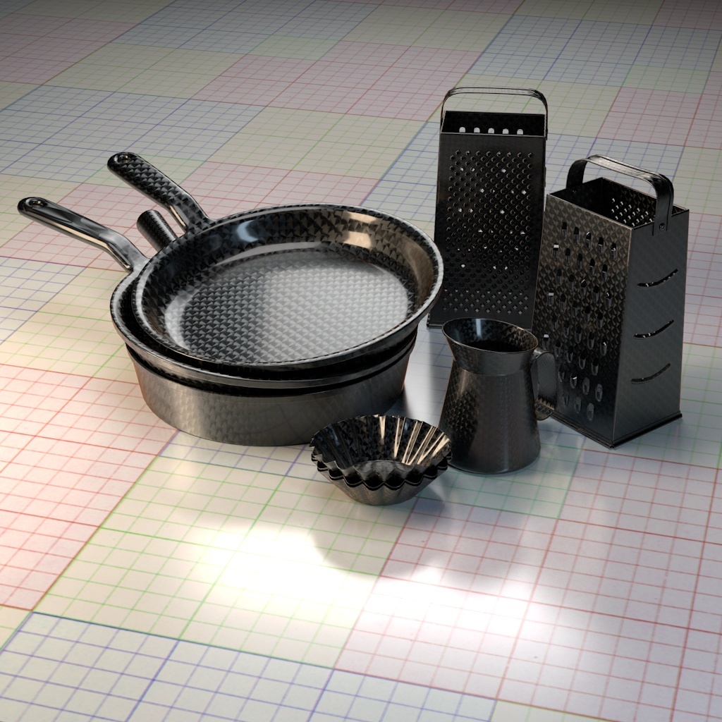
3Delight Metal is a physically plausible material that allows rendering of a whole range of metallic surfaces. This materials differs from other metal material in other renderers in many aspects:
- User friendly parameters such as reflectivity and edge tint instead of difficult to understand complexe index of refraction.
- Ability to render coated metals.
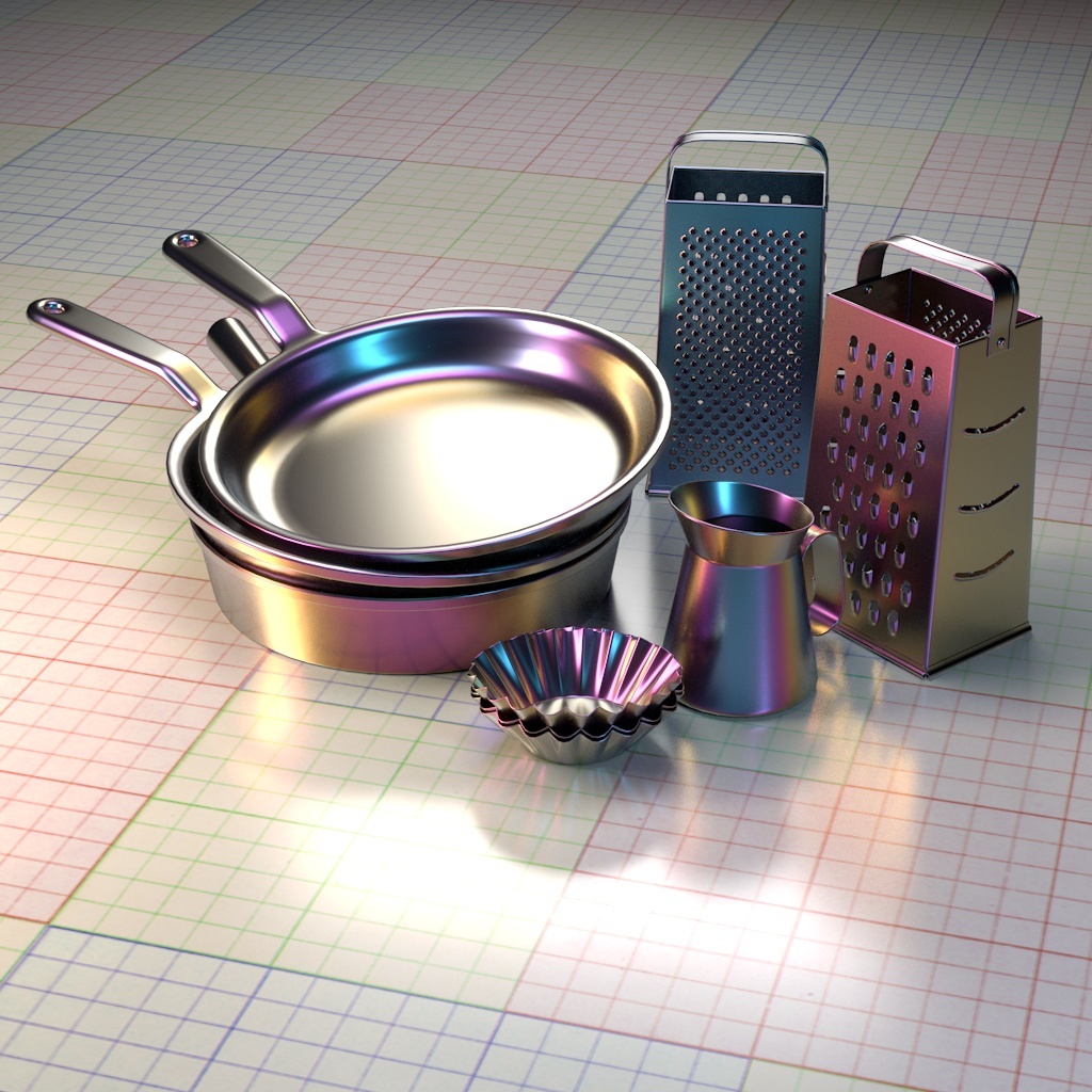
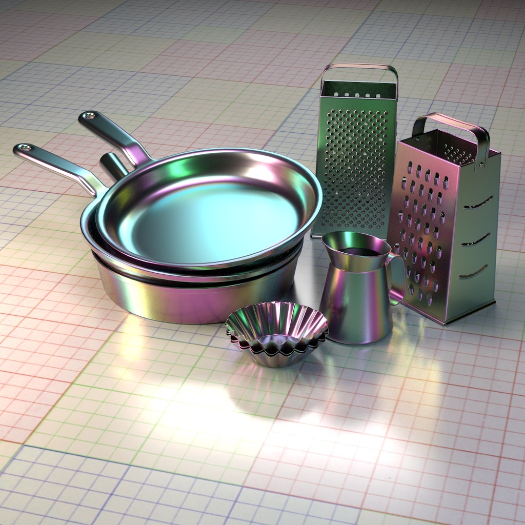
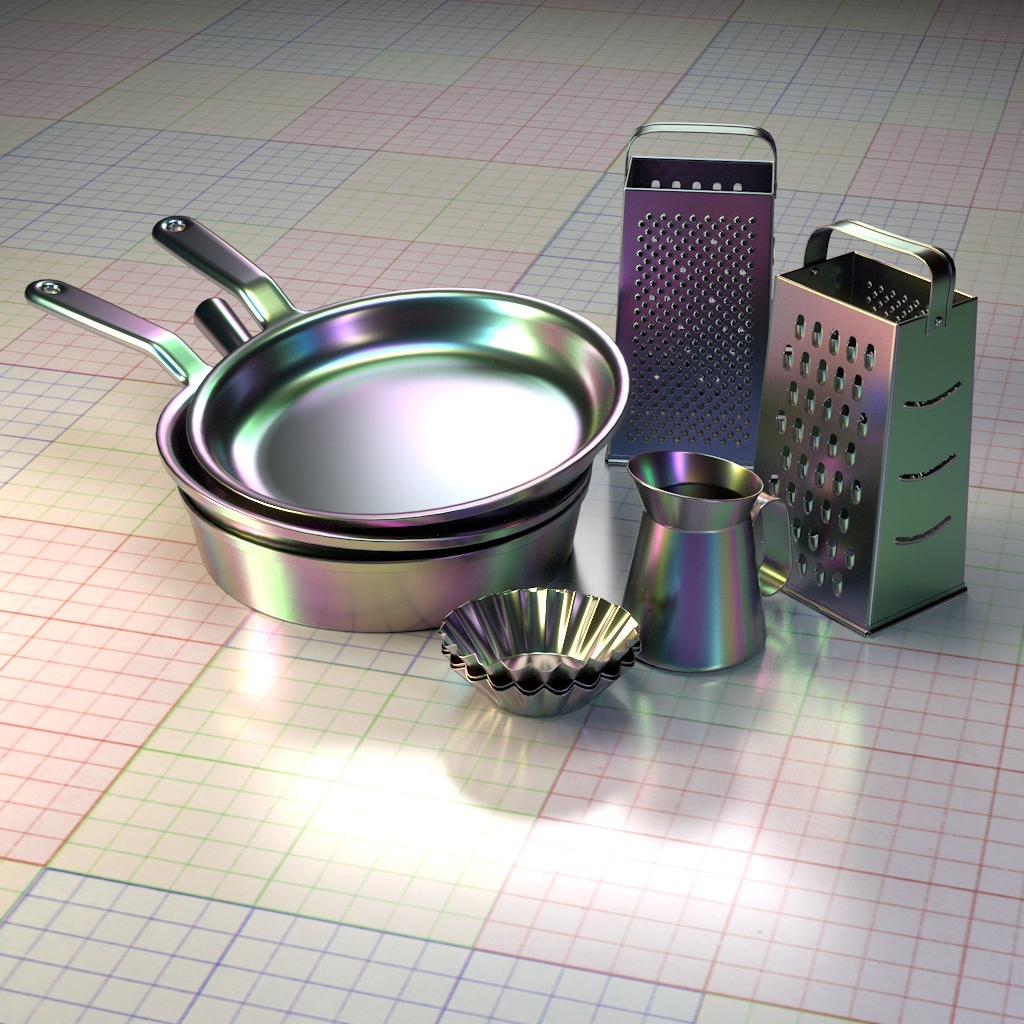
- Ability to render tempered metals. This effect is highly realistic and can render real life tempered metals faithfully.
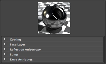
The 3Delight Metal material has three main groups of parameters:
Coating, Base Layer, Reflection Anisotropy and Bump.
Parameters Description
Coating | 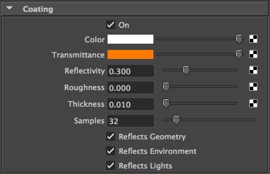 | ||||||
|---|---|---|---|---|---|---|---|
On | Enables or disables the coating feature.
| ||||||
Color | This sets the color of the coating. This means that the color reflected by the coating will be tinted by this quantity.
| ||||||
Transmittance | This sets the colouring of the medium that makes up the coating. Light bouncing from the underlying metal will be tinted by this quantity. Thickness of the coating, described below, will affect how much transmittance color will be visible.
| ||||||
Reflectivity | This sets ratio of light that bounces back when coming from a normal incident angle. For realistic coatings, this quantity should be kept low (only conductors have high reflectivity at normal incidence)
| ||||||
Roughness | Sets the roughness of the coating.
| ||||||
Thickness | Specifies the thickness of the coating. Thicker coatings w
|


Base Layer | 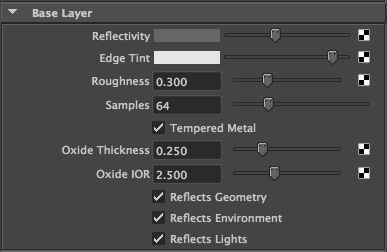 | ||||||||
|---|---|---|---|---|---|---|---|---|---|
Reflectivity | Describes the reflectivity at normal incident angle. This quantity, along with the edge tint below, completely describes physical metal characteristics.
| ||||||||
Edge Tint | Describes how light is tinted at grazing angles.
| ||||||||
Roughness | Describes metal roughness.
| ||||||||
Tempered Metal | Enables or disables tempering.
| ||||||||
Oxide Thickness | The thickness of the oxide layer, in micrometers.
| ||||||||
Oxide IOR | IOR of the oxide. Depends on the metal being rendered. Note that the Presets will automatically set this quantity to the correct value. For example, for iron,
|

Reflection Anisotropy | 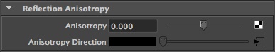 | ||||||||
|---|---|---|---|---|---|---|---|---|---|
Anisotropy |
| ||||||||
Anisotropy Direction |
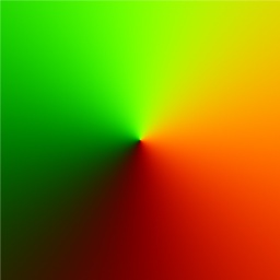
Each channel in the bitmap corresponds to a spatial dimension (X, Y and Z). These spatial dimensions are relative to a varying coordinate system based on the derivatives of position with respect to texture coordinates. Individual components for any direction should be in the range [–1, 1]. But to be encoded into an RGB texture with 8 bits per component, they are mapped into the range [0, 1]. So the XYZ (0, 0, –1) will be remapped to the RGB (0.5, 0.5, 0) values. It's also possible to use an angle texture to convert the direction to the color.
|

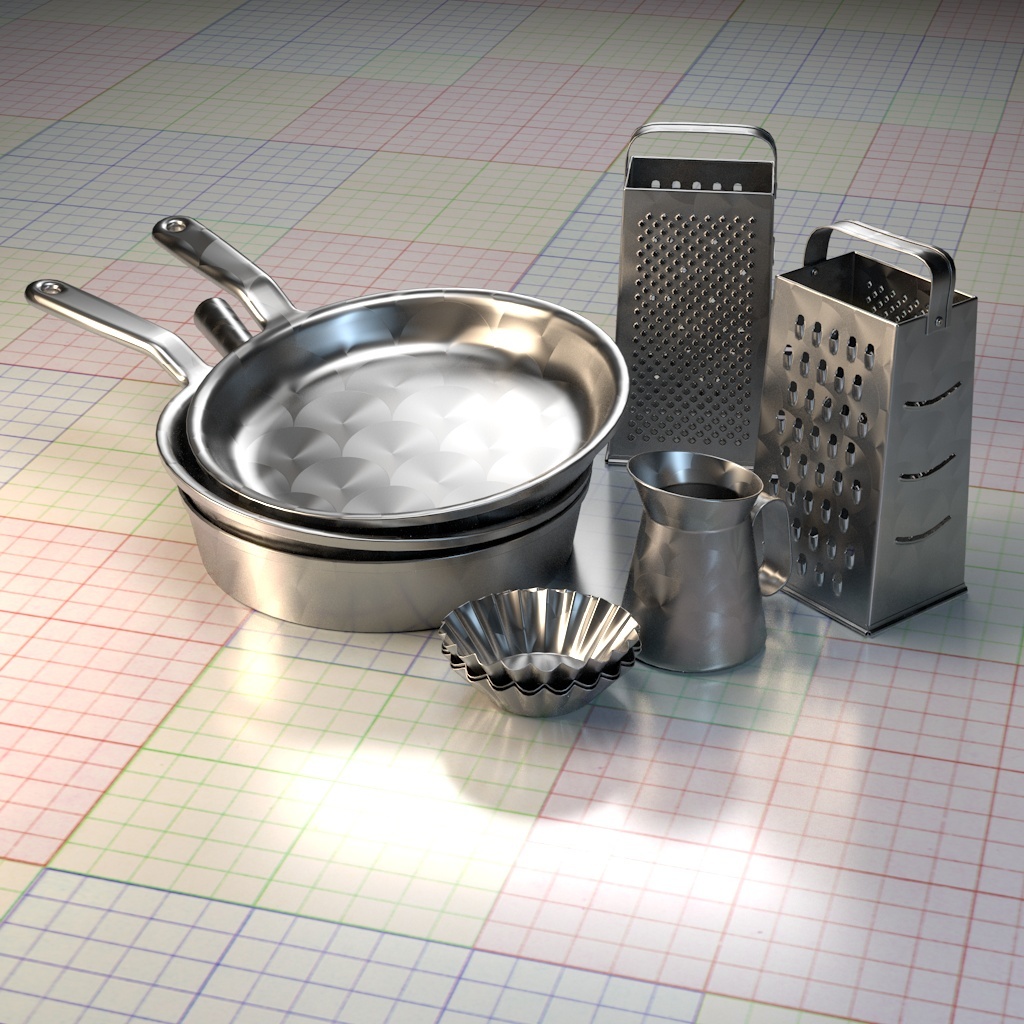

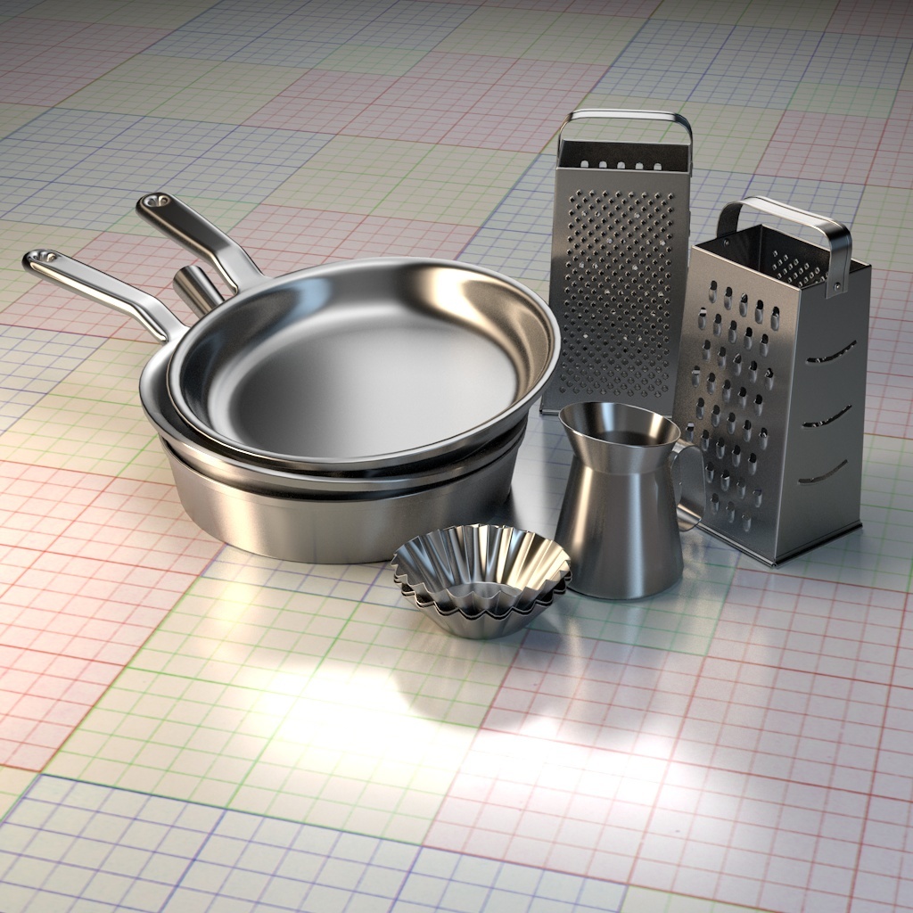
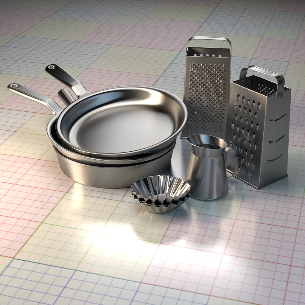
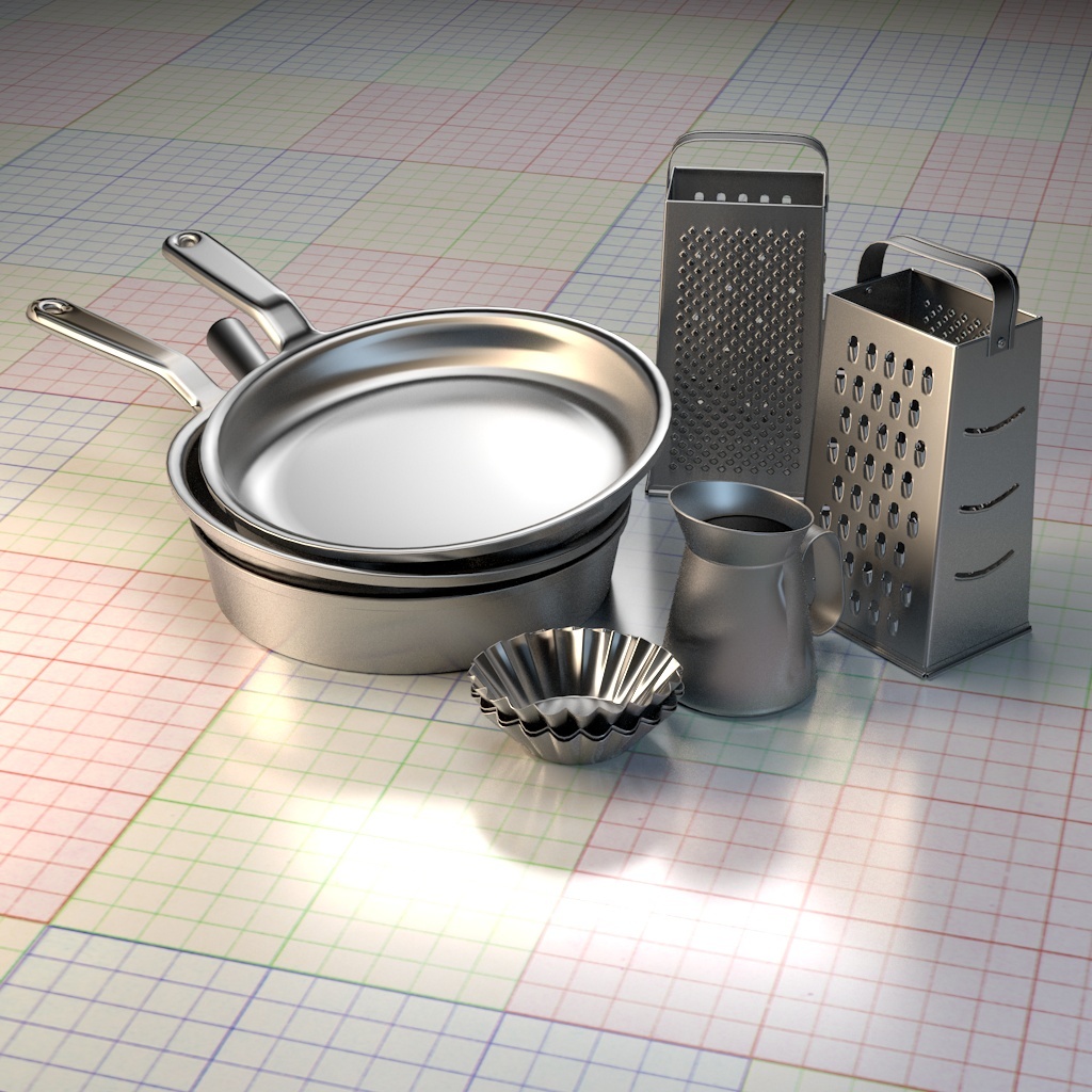
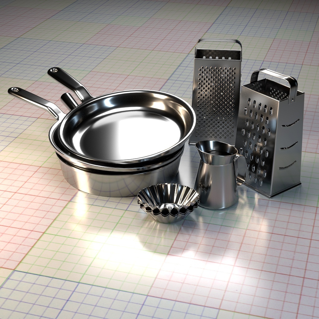
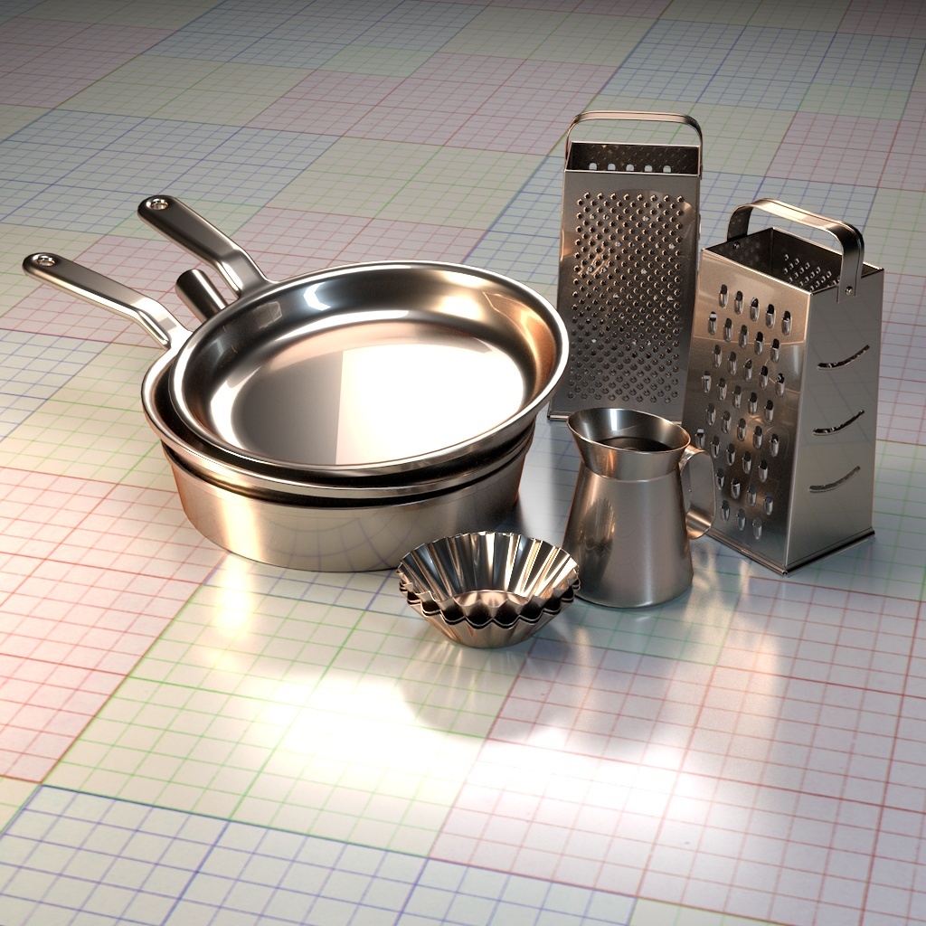
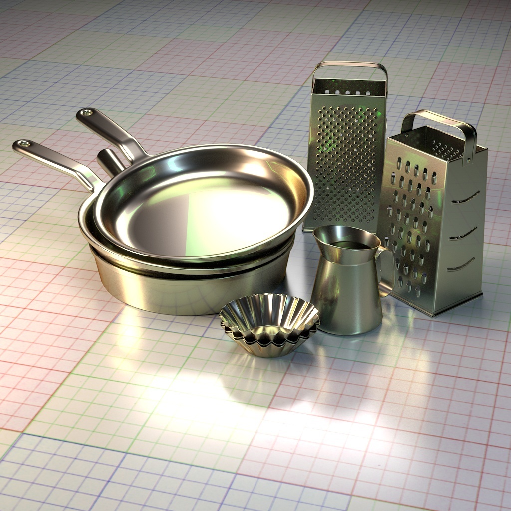
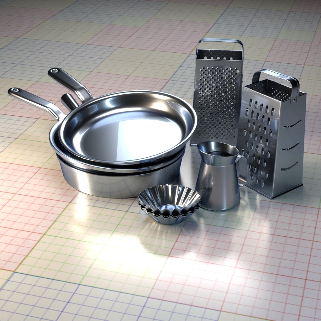
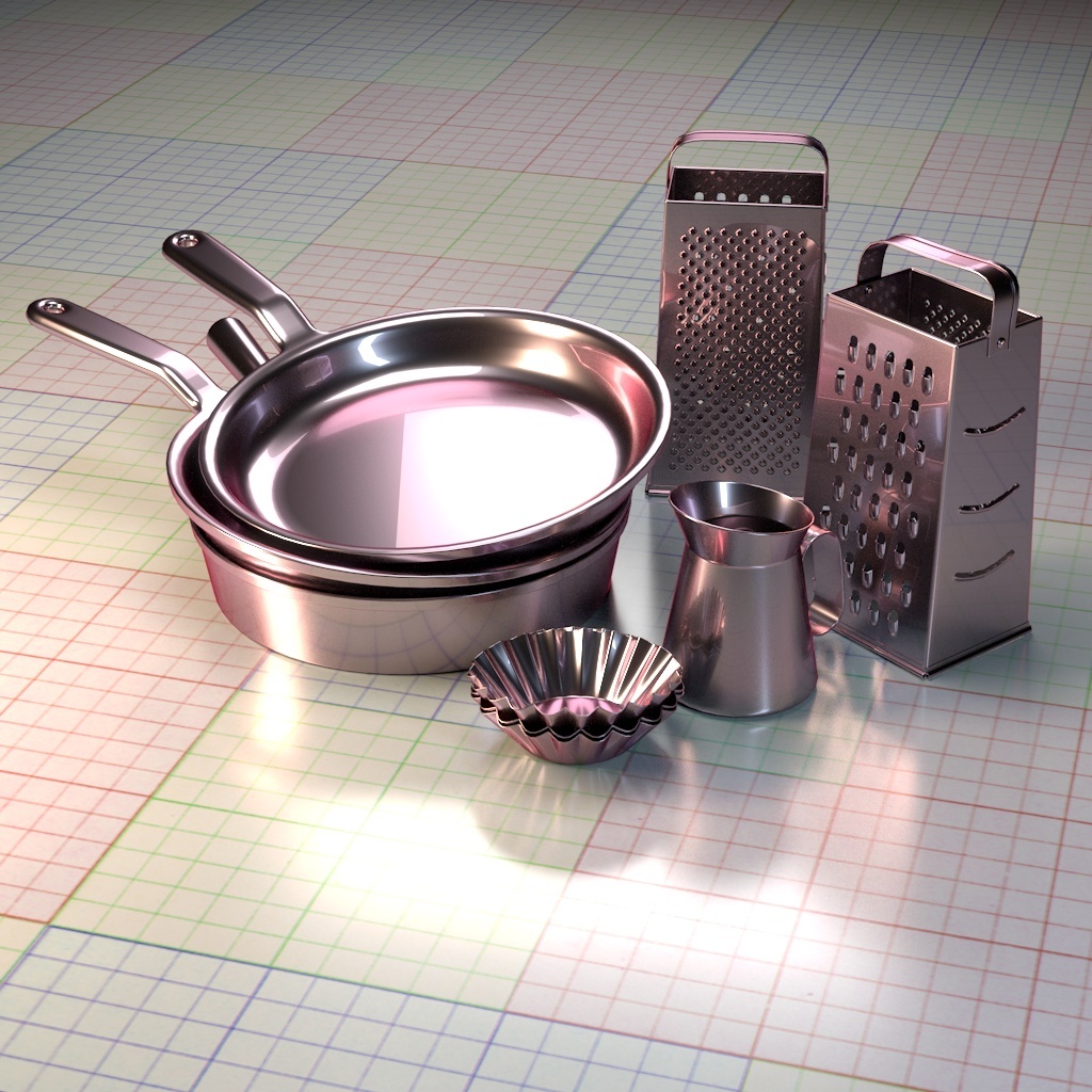
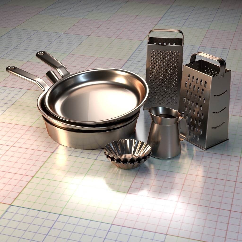
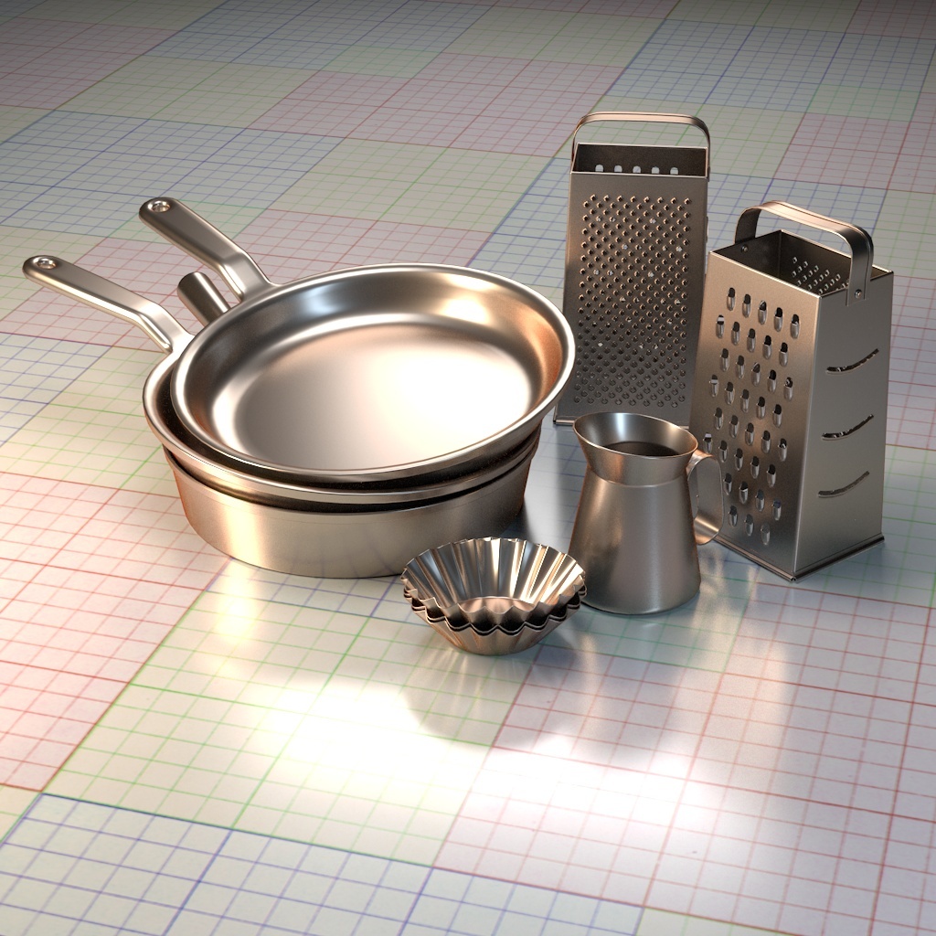
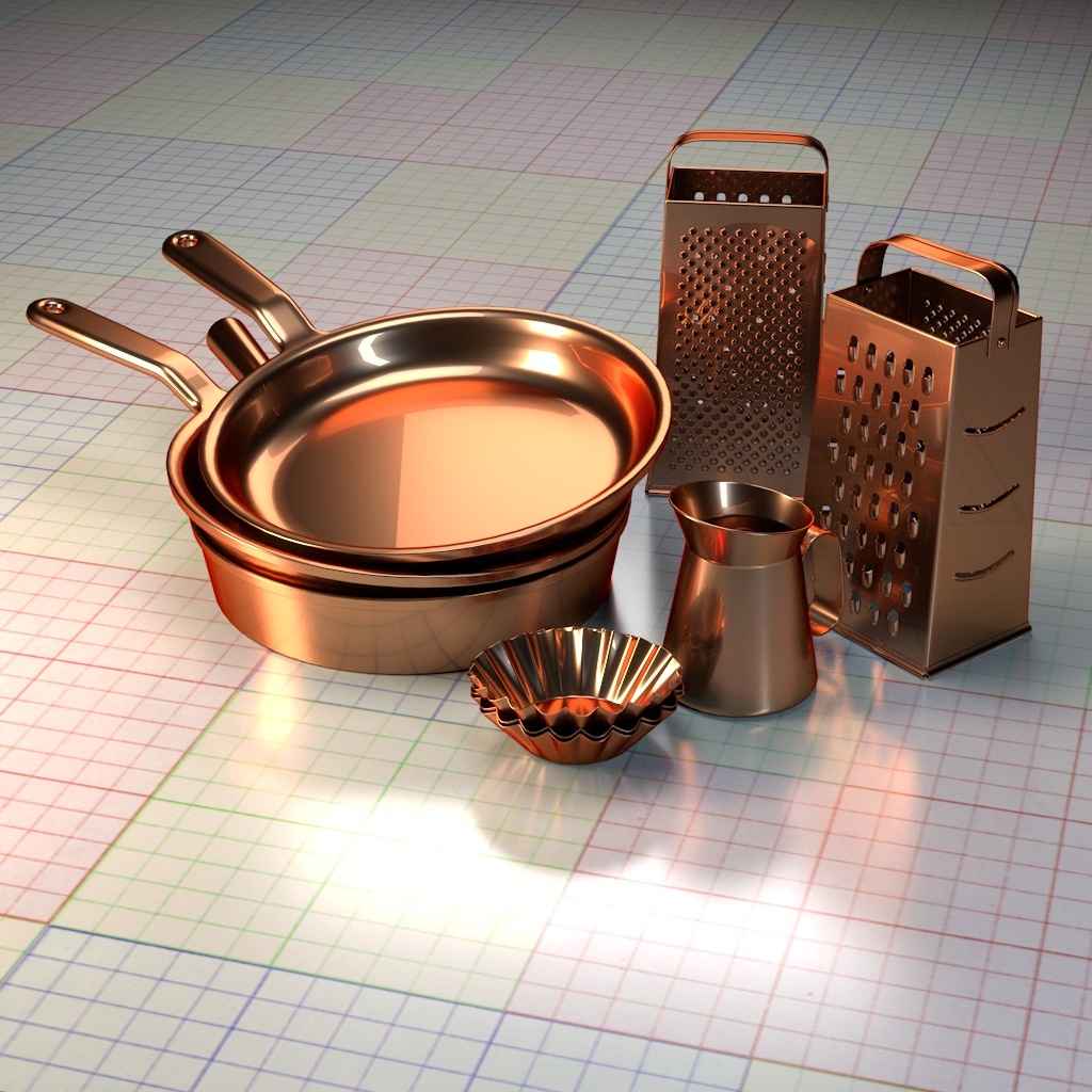
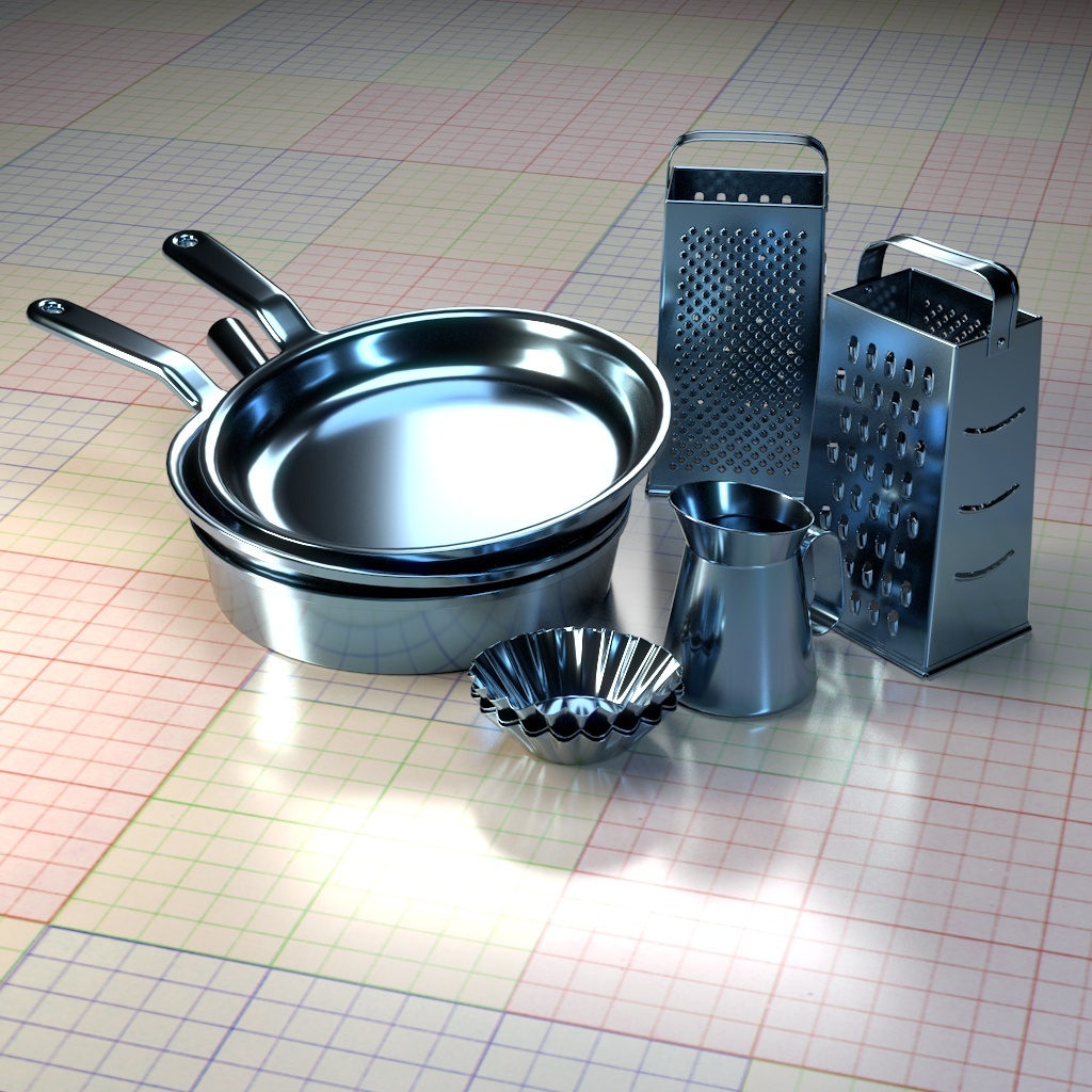
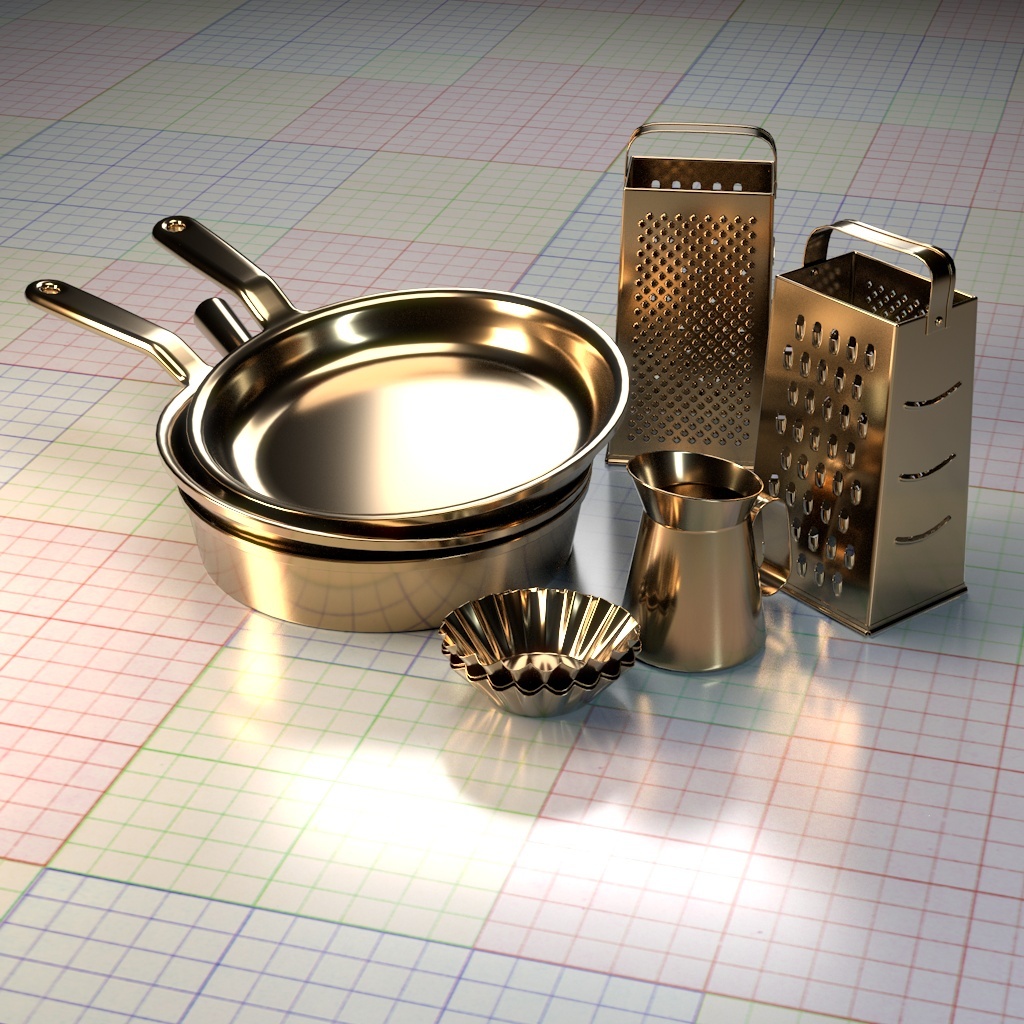
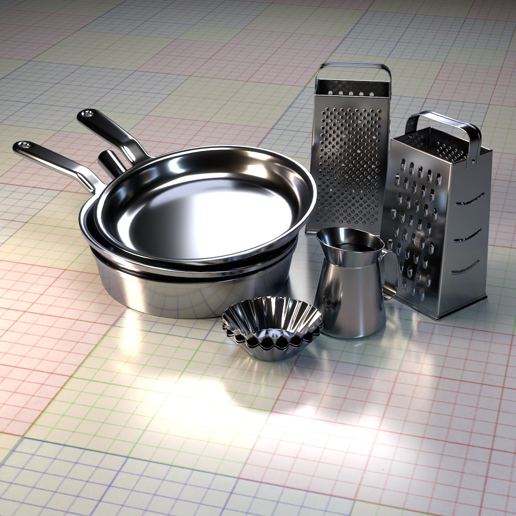
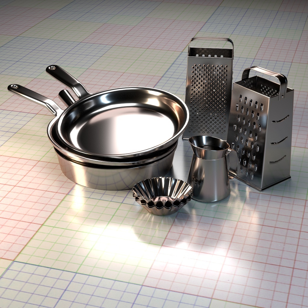
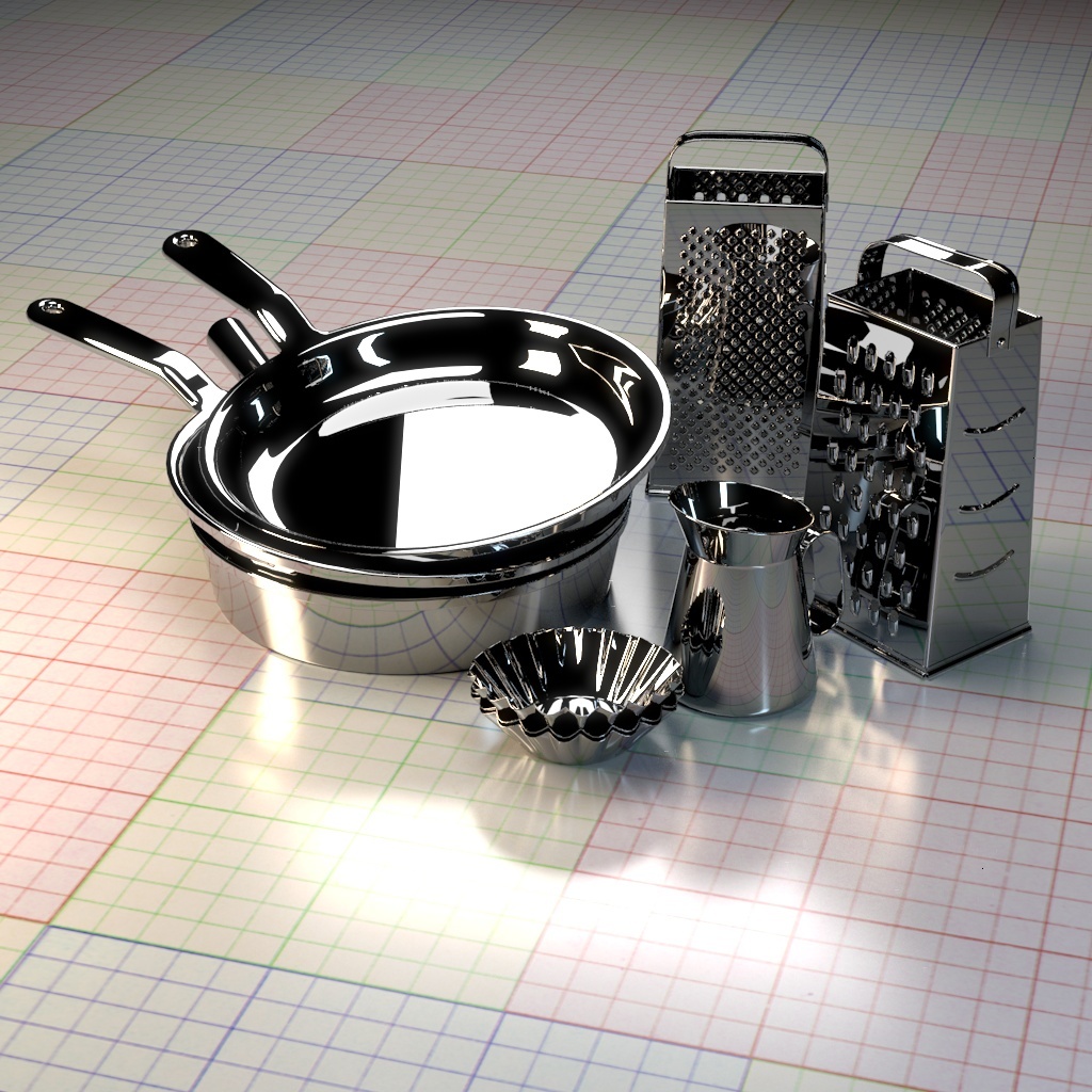
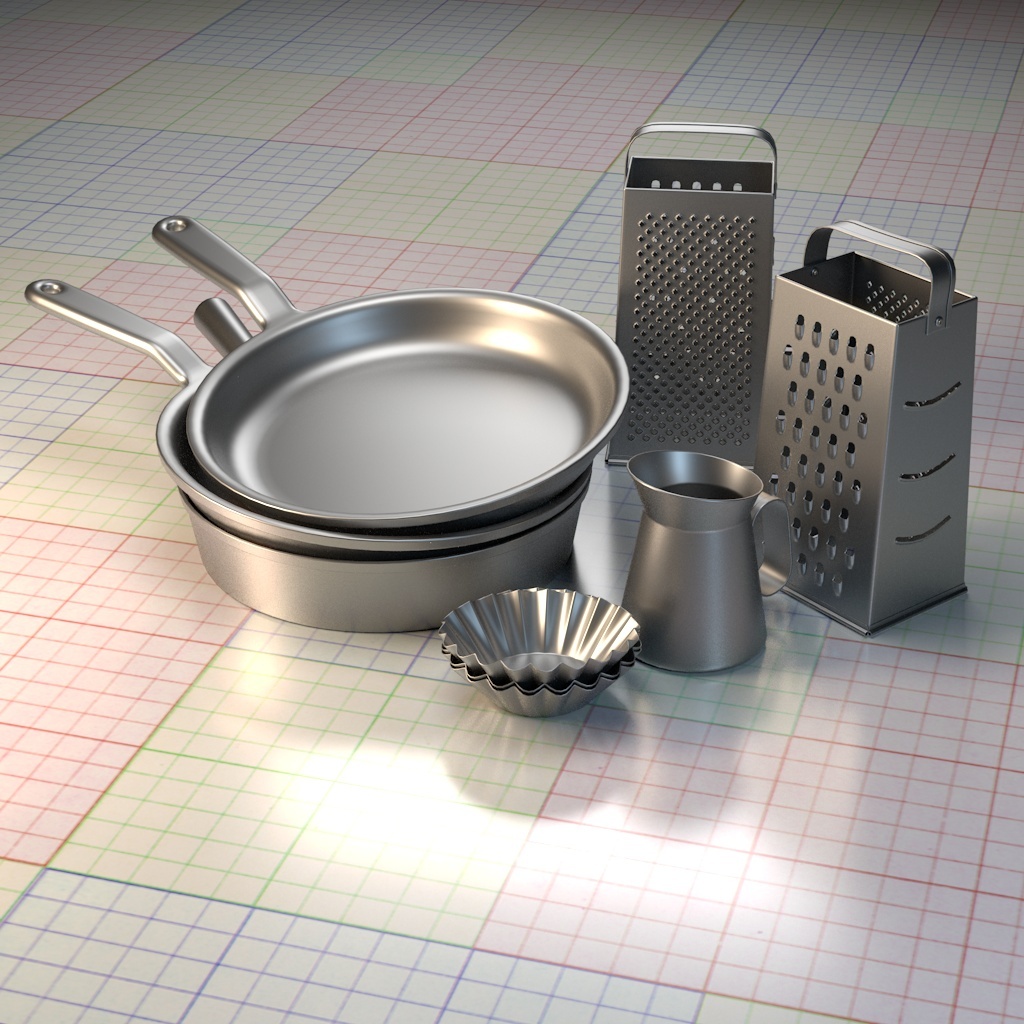
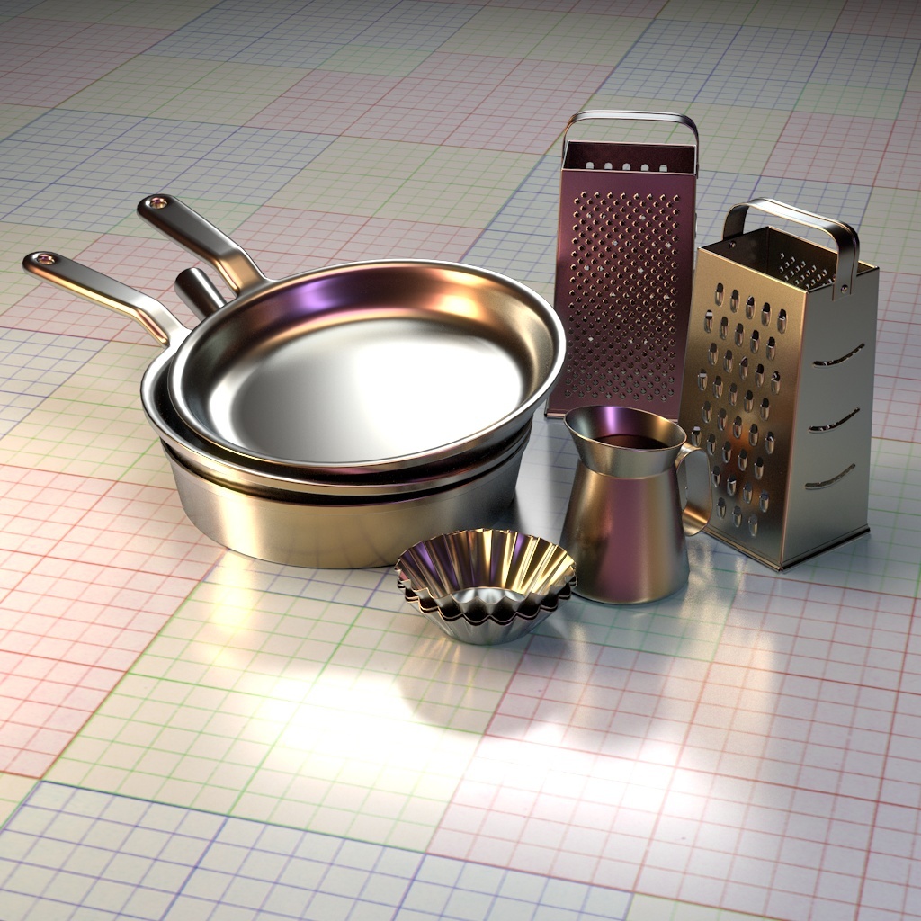
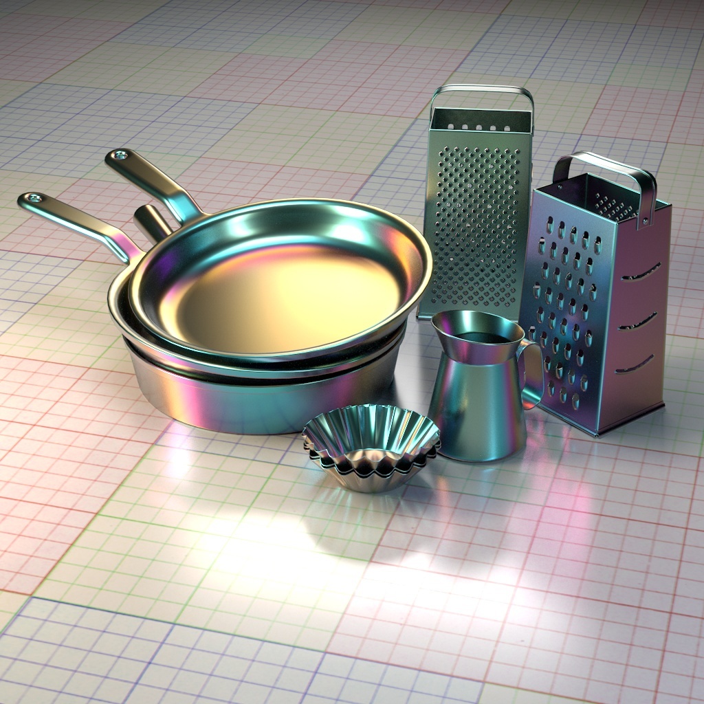
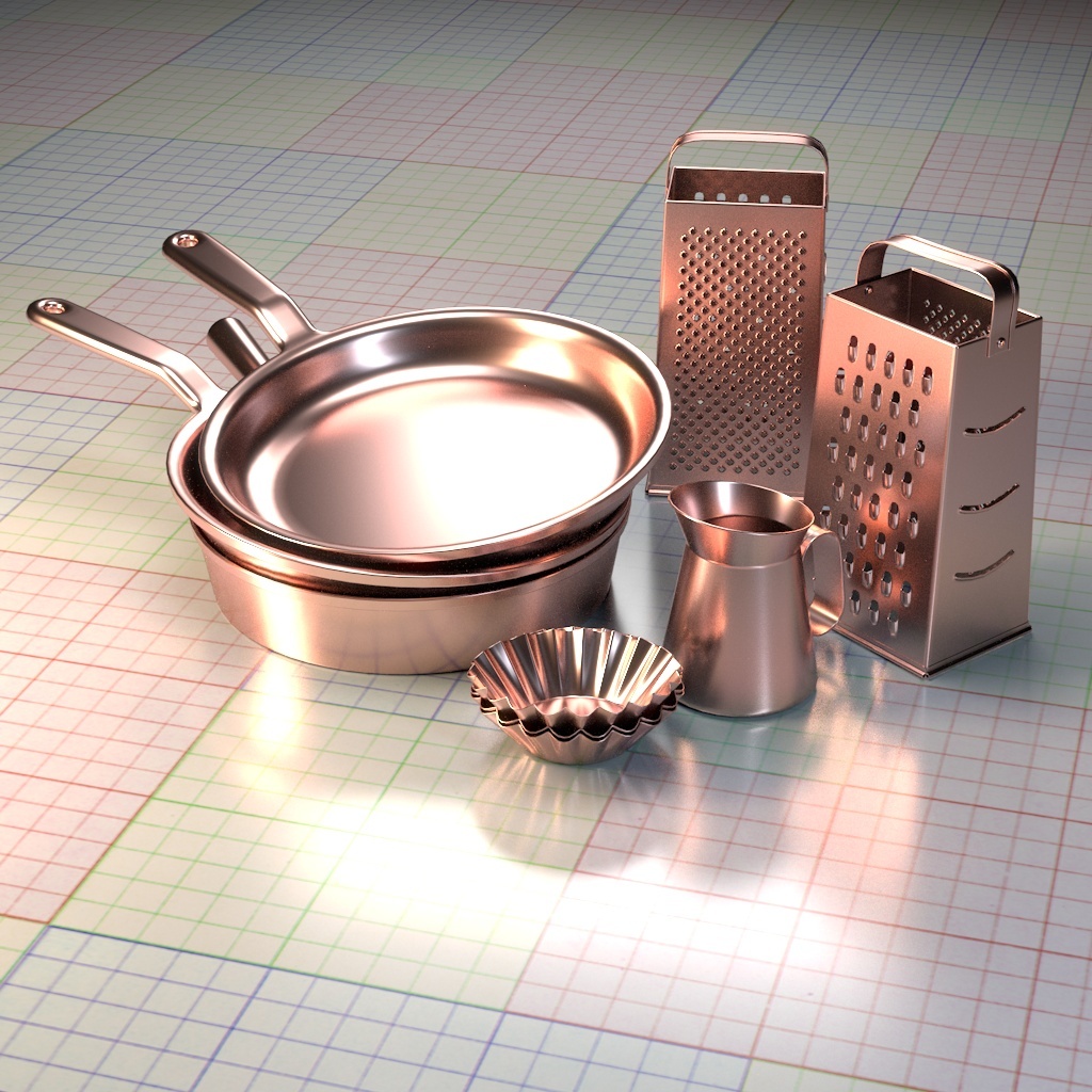
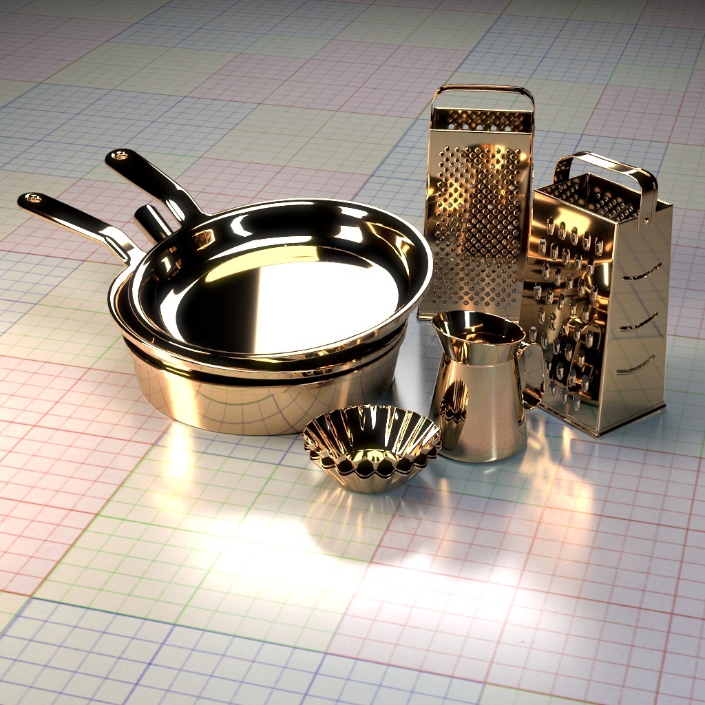
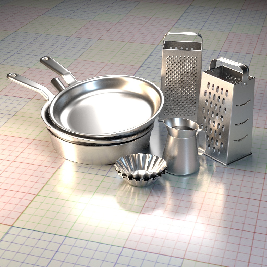
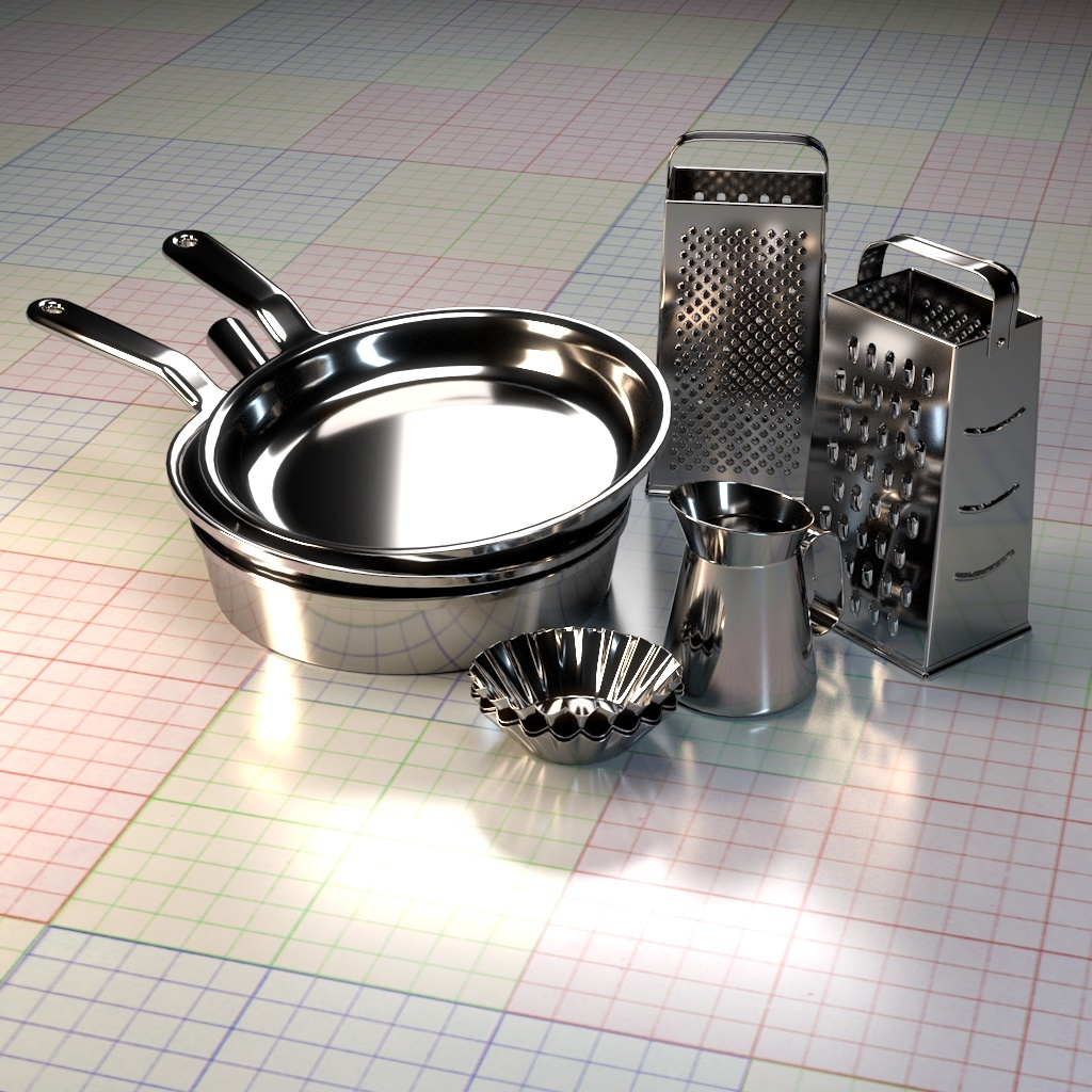
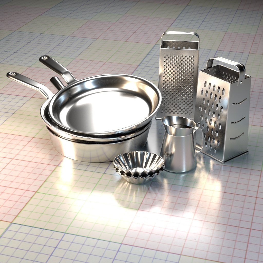
Example Presets
The following images show some of the presets available through the Attribute Editor.
Copper |
Gold |
Aluminium |
Iron |
Silver |
Carbon |
Technical Description
Tempering
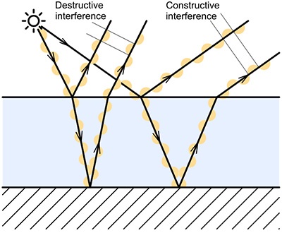
Interference colors are produced when metal is heated and a thin film of metal's oxide forms on the surface. They are dependent on the wavelength and angle of the incident light, the thickness of the oxide film, the refractive indices of the oxide material. This effect is called thin-film interference and occurs when a light is reflected from a thin oxide film.
Figure 1: The source of the tempering colors. When the phase difference between the two reflected beams is an even integer multiple of the wavelength of the beam in the film, then the two reflected beams tend to interfere constructively. If the phase difference between the two reflected beams is an odd integer multiple of the wavelength of light in the film, the beams destructively interfere. |
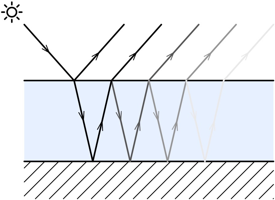
Figure 2: The thin film of the metal's oxide. |
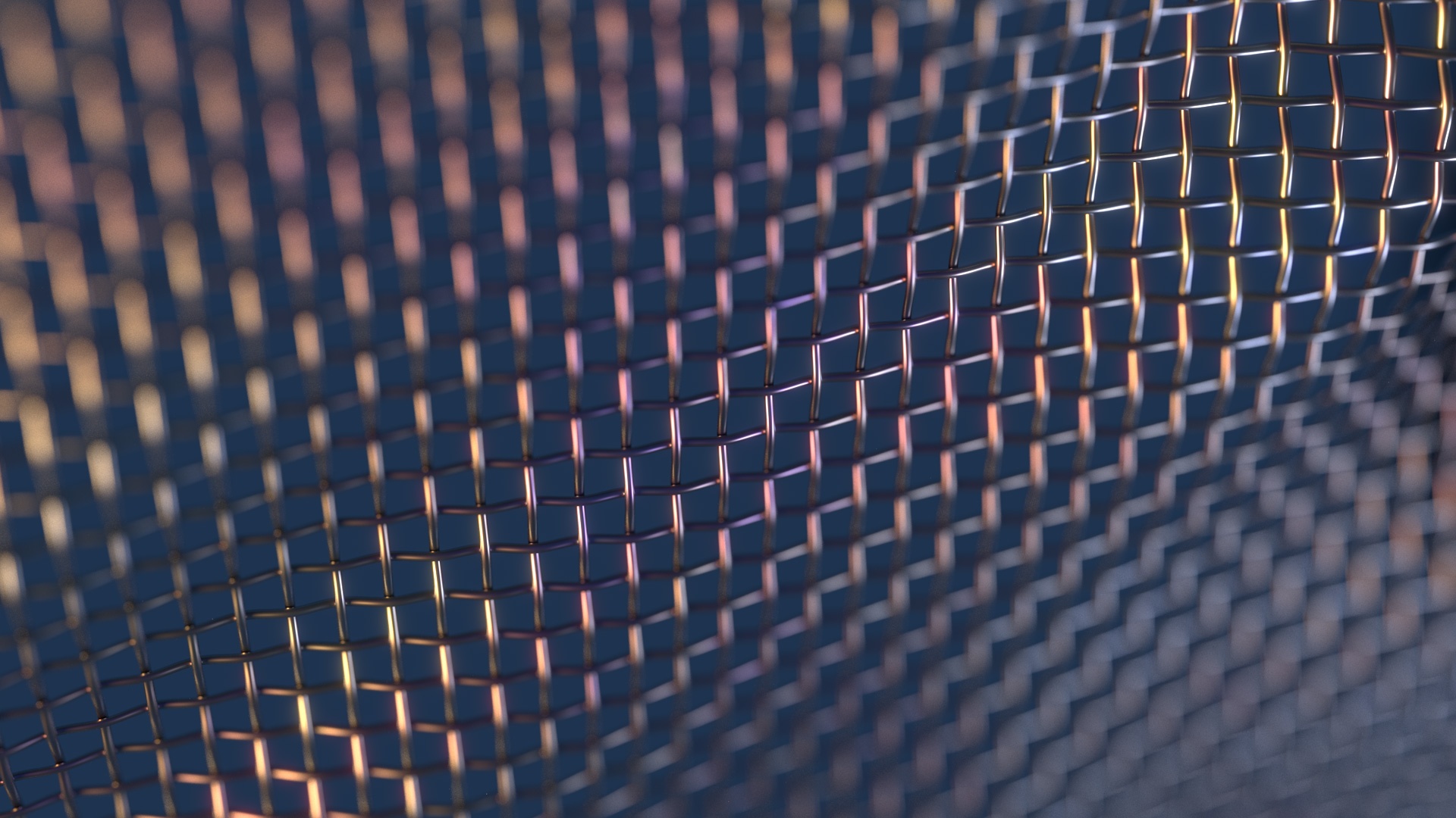
Anisotropy
Anisotropy is the property of being directionally dependent. It allows to set different roughness dependent on the orientation of the surface. In the real world, the anisotropy is generated by a microstructure characteristics arranged in one effective direction. For example, brushed metal objects are polished in such way that there are a lot of parallel scratches in the surface. On CDs, the microstructure is produced by the tracks containing the data.