General

This panel controls the color, opacity and “sidedness” of attached object.
Color
This attribute specifies the surface color (Cs) of the attached objects. This color can be overridden by the attached shader; shaders translated from Maya Hypershade shaders will usually multiply their base shader color with Cs. This means that a single hypershade shader can have a white base color and be assigned to multiple objects; each object can defined their own surface color value so they all have the same shading look but a unique color. Photons will only use this color and ignore both types of shaders. The default color color is white (‘1.0, 1.0, 1.0’).
Opacity
This attribute specifies the surface opacity (Os) of the attached objects. Darker values are less opaque. This color can be overridden by the attached shader. The default opacity is completely opaque (‘1.0, 1.0, 1.0’).
Double Sided
This attribute controls if only the object’s front side (the side pointed by the direction of the normal) is visible, or if both the front and back sides are visible. When this attribute is on, the object is visible on both sides. This attribute is on by default.
Double Shaded
When this attribute is on, each surface is shaded twice: once with the normals in their usual direction and once with the normals reversed. This allows thickness to be given to a surface with displacement or to avoid shading artifacts where a transparent surface changes orientation. This attribute is off by default.
Reverse Orientation
If the surface is one sided and this attribute is turned on, its orientation will be reversed. This attribute is off by default and has no effect when the "Double Sided" attribute is turned on.
Quality
This panel controls how finely this geometry will be tessellated and how surface derivatives will be computed.
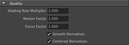
Shading Rate Multiplier
The shading rate used to shade objects attached to this node is determined by multiplying the value of this attribute with the shading rate specified in the ‘Quality’ panel of the render pass (see Section 3.9.3.3 [Render Pass Quality], page 61). For example, if this value is set to ‘2.0’ and the shading rate in the render pass is ‘1.5’ then the effective shading rate for this object will be ‘3.0’. The default value for this attribute is ‘1.0’.
Motion Factor
This attribute specifies how the shading rate of an object increases when moving rapidly. Since a fast moving object will be heavily blurred, it makes sense to use a coarser shading rate in that case. The same can be said about an object that is out of focus due to the chosen depth of field. The default setting of ‘1.0’ is is a good quality versus performance compromise.
Focus Factor
This attribute specifies how the shading rate increase as an object gets blurred by depth of field. The default setting of ‘1.0’ is a good quality versus perfor- mance compromise.
Smooth Derivatives
Centered Derivatives
Enables smooth and centered derivatives, respectively. By default, these two attributes are on; more details about these two parameters can be found in 3Delight User’s Manual.
Visibility

Matte Object
When this attribute is on, the attached objects act as a matte holdout. Matte objects are not shaded and behave as if they were completely opaque, hiding any objects behind them, but appear in the image as transparent black pixels. This attribute is off by default.
Composite Objects Behind
When this attribute is off, the attached objects, even if semi or completely transparent, will mask all objects behind them. This attribute is on by default.
Visible To Camera
If this attribute is turned on, the attached objects are visible to the camera. By default, this attribute is on. Note that turning this attribute off will simply make the attached objects invisible to the camera; they will still be exported to RIB.
Transmission Rays (shadows)
This attribute specifies the visibility of the object relative to ray traced shadow rays, or transmission rays.
Specular Rays (reflections and refractions)
This attribute specifies the visibility of the object relative to specular ray traced rays (both reflections and refractions). Objects shaded using Maya’s Hypershade can further refine if they are visible in reflections and refractions using the relevant "render stats"; see Section 5.4.1 [Maya Render Stats and Geometry Attribute Nodes], page 128.
Diffuse Rays
This attribute specifies the visibility of the object relative to diffuse ray traced rays, which are used to compute indirect illumination effects.
Visible To Photons
When this attribute is on, the attached objects surfaces will interact with pho- tons according to the selected "Shading Model" (see Global Illumination). This attribute is on by default. Possible values for transmission, specular and diffuse rays are summarized in the following table.
| Value | Description |
|---|---|
| Invisible | The object is not visible to ray traced rays. |
| Opaque | The object is visible to ray traced rays; it is considered fully opaque and white. |
| Primitive Color | The object is visible to ray traced rays; these rays will be affected by the object’s "Color" and "Opacity" attributes in a geometry attribute node (see General). |
| Shader Color | The most expensive mode: the renderer will evaluate the surface using the attached shader to determine the color and opacity. This is the default option. |
Lighting

The Illumination From attribute controls how the attached objects are illuminated. When ‘<light linker>’ is selected, the objects are illuminated by lights linked to them. When Maya object sets are defined in the scene, they will also be listed in this option menu; assigning this attribute to a set will illuminate attached objects with the light sources contained in the set. By default, this attribute is set to ‘<light linker>’.
Raytracing

Raytrace Motion Blur
This attribute enables or disables motion blur for traced rays. For example, a moving object as seen in a mirror will only show motion blur if this option is enabled.
Raytrace Displacements
When this attribute is checked, it enables ray tracing of true geometric displacements. The default is to ray-trace displacements as bump maps (a displaced surface appears bump mapped in a mirror reflection). Enabling this feature makes ray tracing slower and forces 3delight to use more memory so this option should be used with care.
Raytrace Bias
Specifies a bias for rays starting point to avoid potentially erroneous intersec- tions with emitting surface. The default value is ‘0.01’.
Trace subset
This attribute is used to select one or several Maya object sets that is used to narrow down what objects are visible to ray traced rays. This feature can be useful when a scene is using referenced objects that already have their "Trans- mission" attribute correctly set, but only part of these objects are needed to be visible to ray traced rays in this specific scene. The "Trace subset" option menu has the following values available:
‘All Objects’
ll objects whose "Transmission" and "Visible To Reflections" at- tributes have been properly set will be visible to ray traced rays. This is the default.
‘Objects in selected sets’
Only objects in the selected Maya sets and whose "Transmission" and "Visible To Reflections" attributes have been properly set will be visible to ray traced rays. The "Select Sets" button can be used to select the desired Maya sets to include.
‘Objects not in selected sets’
Only objects that are not in the selected Maya sets and whose "Transmission" and "Visible To Reflections" attributes have been properly set will be visible to ray traced rays. The "Select Sets" button can be used to select the desired Maya sets to exclude.
Motion Blur

Transformation Blur
This attribute controls if the attached objects are subject to transformation blur. Refer to Section 3.9.3.4 [Render Pass Motion Blur], page 63 for more information about motion blur.
Deformation Blur
This attribute controls if the attached objects are subject to deformation blur. Refer to Section 3.9.3.4 [Render Pass Motion Blur], page 63 for more informa- tion about motion blur.
| Value | Description |
|---|---|
| On | The attached objects will be motion blurred, regardless of the corresponding setting in the render pass. |
| Off | The attached objects will not be motion blurred, regardless of the corresponding setting in the render pass. |
| Inherit | The attached objects are motion blurred only if the corresponding attribute is turned on in the render pass. This is the default. |
Global Illumination
The following attributes are deprecated. A more user friendly method for the functions below will be available soon.

Photon Color
This attribute defines how the photons will receive their color and opacity. The available choices are:
`Primitive Color & Opacity'
The photons get their color from Cs and their opacity from Os. It is possible to define these two attributes using the "Color" and "Opacity" attributes, respectively (see [Color], page 19 and [Opac- ity], page 19). This value should be preferred as it is faster to compute.
‘Shader'
The photons get their color and opacity from the attached surface shader. This is the default.
Photon Estimator
The number of photons that shading operations relying on photons will use. The default number of photons is 50.
Shading Model
This attribute determines how the attached objects surfaces will interact with photons. Note that for photons to interact with surfaces you have to make them visible to photons (they are by default) in the visibility attribute (see Section 3.5.5 [Geometry Attribute Node Visibility], page 21). The available shading models are summarized in the table below.
| Value | Description |
|---|---|
| Transparent | There will be no interactions with photons. This is the default. |
| Matte | Generates a diffuse reflection and is fine for color bleeding effects. |
| Chrome | Reflects all photons like a mirror. It also generate caustics |
| Glass | This value will partly reflect photons, partly refract them. It also generate caustics. |
| Water | Similar to `Glass' but has the refraction index of water. |
Displacement

Displacement Bound
This attribute specifies the displacement bound for the attached objects, which is the amount by which the bounding box of each object should be increased to include the displaced surfaces. Failure to provide the renderer with a decent value will result in shading artifacts (when the value is too small) or inefficiency (when the value is too large). When the displacement bound is too small, 3Delight issues an error message stating by how much the value is too small; it is recommended to use this information to assign a reasonable bound. The default value is ‘0.0’, which is fine only if the surfaces are not displaced
Bound Space
This attribute defines in which space the Displacement Bound parameter is defined. The default space is ‘shader’.
Culling And Dicing
These attributes are only active when using the REYES render engine.
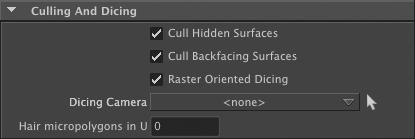
Cull Hidden Surfaces
When this attribute is off, the attached objects that are in the viewing frustum but completely hidden (behind another object) will still be rendered and shaded. When this attribute is on, hidden objects will be dismissed. This is the default. The only reason to this feature off is when “baking” expensive shaders. More about baking in 3Delight User’s Manual.
Cull Backfacing Surfaces
When this attribute is off, the one-sided attached objects that are in the viewing frustum and backfacing will still be rendered and shaded. When this attribute is on, one-sided, backfacing objects will be dismissed. This is the default. The only reason to this feature off is when “baking” expensive shaders. More about baking in 3Delight User’s Manual.
Raster Oriented Dicing
This attributes enables enables or disables “raster oriented” tessellation. When tessellation is raster oriented, 3delight considers the object as viewed from the camera to compute the tessellation factors. This means that objects (or parts of objects) facing the camera will be tessellated more densely than tilted objects. By default, this attribute is on. A good reason to disable this feature is when displaced surfaces loose detail at object edges. For the more advanced users only.
Dicing Camera
This attribute specifies the camera to be used to tessellate the attached objects.
Micropolygons in U
This attribute forces 3delight to use a certain number of micro-polygons on the width of each curve. The default value is ‘1’, which is the same as disabling "Hair Dicing".
Geometry
The attributes in this category and its subcategories have a direct effect on how the objects in Maya are translated to RenderMan primitives. For this reason, they have no effect on the geometry imported in the scene by a ‘RIB Archive Node’, and they will not be affected by the "Ignored Archived Geometry Attributes".

Output Geometry
When this attribute is off, the attributes of the "Geometry Attribute Node" will be output but not the geometry of the objects that are attached to it. By default, this attribute is on.
Output Faceid
Turning on this attribute will produce a primitive variable named "faceid" that define one id number per face of the primitive. This variable can be used with the Edge Detection feature of a display to produce a wireframe outline of the primitive simply by setting the "Detected Variable" attribute to ‘float faceid’. See [Edge Detection], page 74 for details.
Polygons

Use Current UVset
When this attribute is on, the current UV set is exported as the ‘s' and `t’ primitive variables; no other UV set will be exported. When it is off, the default UV set will be exported as ‘s, t’ primitive variables; extra UV sets are exported as an array of ‘u’ values named ‘uvsets_u’ and ‘v’ values named ‘uvsets_v’; the set names are exported in a ‘uvsets_name’ string array. This attribute is off by default, and is ignored when "Output All UVsets" is turned on.
Output All UVsets
When this attribute is turned on, the UV sets are output as follows:
- The default UV set is output as ‘s, t’ primitive variables.
- Each other UV set is output as a float array bearing the same name as the
UV set being exported.
When this attribute is off, the behaviour defined by the "Use Current UVset" attribute prevails. This attribute is off by default.
Output Vertex Color
When this attribute is checked and the attached object is a polygon mesh, any color sets it contains that defines per-vertex color will be exported to rendering. Each color set will be exported as a color array bearing the same name as the color set. Additionally, a float array is also exported; its name consists of the color set name with ‘ alpha’ appended to it. It contains ‘0’s for vertices where the color set is not defined, and ‘1’s were it is defined. This attribute is off by default. See Section 5.4.3 [Exporting Per-Vertex Attributes on Polygon Meshes], page 131 for an example on how to use this.
Poly As Subd
When this attribute is checked, 3Delight for Maya will consider this polygonal geometry as being a smooth subdivision surface. If this attribute is off, the polygon mesh will be considered as just that, a polygon mesh. This attribute is ignored when the attached object is not a polygonal geometry, and it is off by default.
Smooth UVs
High quality rendering of textured subdivision surfaces cannot be accomplished without properly interpolated texture coordinates. This control enables precisely that. Possible values are summarized in the table below.
| Value | Description |
|---|---|
| No | No smoothing is performed. This will not lead to high quality results but has the advantage of not stretching texture coordinates over face boundaries. |
| Partial | Will ask 3Delight to perform some work to minimize UV distortion on the surface. Seams are left untouched. This is the default. |
| Full | Will use more advanced algorithms to minimize distortion of UV coordinates at texture seams. This will usually yield better results but might cause some textures to look misplaced. It is best to try it to see what it does. note: This also controls the interpolation of vertex colors and other quan- tities that are attached to geometry’s vertices. |
Export Hard Edges (for Poly as Subd)
If the attached object is made of polygonal geometry that contains hard edges, setting this attribute to on will export the hard edges. The effect of this at- tribute is similar to the "Keep Hard Edges" attribute of a "Maya Subdiv Proxy" node. This attribute is ignored if the "Poly As Subd" attribute is turned off (it is off by default).
Export Creases (for Poly As Subd)
If the attached object is made of polygonal geometry and is connected to a sub- division proxy containing creases, turning this attribute on will export creases (creases on edges and vertices are exported). This attribute is ignored if the "Poly As Subd" is turned off (it is off by default).
Interpolate Boundary
When this attribute is on, boundary edges and vertices are infinitely sharp. This attribute is on by default.
Polygons Wireframe

The attributes in this panel can be used to generate a wireframe on polygon mesh objects. The edge detection feature of a display can be used to render unshaded wireframes instead; see [Edge Detection], page 74 for details.
Output Wireframe
When this attribute is on, curve primitives that follow the polygon edges are output along with the mesh. These new primitives are shaded like the polygon mesh. This attribute is off by default.
Raster Space Wireframe
This attribute determines how the "Wireframe Width" attribute is interpreted. When "Raster Space Wireframe" is on, the width is expressed in pixels. When it is off, the width is expressed in object space. In other words, turning on this attribute means that the wireframe width will remain constant even when the object or the camera is moving. This attribute is on by default.
Wireframe Width
This attribute defines the width or the wireframe. Its value is interpreted in pixels or in object space units depending on what the "Raster Space Wireframe" attribute is set to. This attribute is set to ‘1.0’ by default.
NURBS
This attribute is deprecated.

When Normalize Nurbs Basis is on , the UV range of any attached NURBS patch will be brought back to a range between 0 and 1. This attribute is on by default.
Curves
Output Maya Curves
When checked, render Maya curves using 3Delight. This is only meaningful when this attribute is attached to a Maya curves geometry.
Start Width
End Width
If Output Maya Curves is checked, specifies the width of the curves at their roots and tips, respectively.
Particles

Particle Render Type
This attribute can be used to override the render type set in the particle shape.
| Value | Description |
|---|---|
| Inherit | Use the render type set in the particle shape |
| Points | Render using 3Delight's lightweight primitive |
| Spheres | Render using 3Delight's spheres |
| Streak | Render as streaks (lines) |
| Disk | Render as 3Delight's disk |
| Blobby | Render as 3Delight's blobbies |
Particle Size Space
This attribute is used to specify the space in which the size of the particles is expressed. Available values are summerized in the table below.
| Value | Description |
|---|---|
Raster Space | The particle size will be taken as pixels. The particle size will remain the same, even if the distance between the camera and the particle system changes. |
Object Space | The particle size is expressed in the object space. Scale transforms affecting the particle system will influence the particle size. This is the default. |
World Space | The particle size is expressed in world space. |
Particle Size Override
When this attribute exists, it defines the size of the particles, overriding what is defined in the attached particle system shape. This can be useful when the particle size needs to be expressed in object space or world space, since the particle shape "Point Size" attribute has a minimum of 1, which can be too large for size in object or world space.
Paticle Size Scale
This attribute specifies a scaling facotr that is applied to per particle or per system size value. The default scale factor is ‘1.0’.
Render As Volumes In DSMs
Particles rendered into a deep shadow map will appear as flat objects. Thus, when viewed from a different location than the light, the half closer to the light will not be shadowed while the other half will have self-shadowing. When this attribute is on, particles will be exported with a thickness equivalent to the width, height or radius or the particle, which should generally be enough to work around the shadowing problem. Note that this only has effect when rendering deep shadow maps, and only when the "Volume Interpretation" attribute is set to ‘continuous’. See [Light Attribute Volume Interpretation], page 49.
Render nCloth as Particles
When this attribute is on, any attached nCloth shape will be rendered as a par- ticle system. The nCloth shape’s "Thickness" and "Self Collide Width Scale" attributes are used to compute the particle size. This attribute is off by default.
Per Particle Color as Surface Color
When this attribute is on, the "rgbPP" particle system attribute will be output in the surface color primitive variable (‘Cs’). Turning off this attribute will output the "rgbPP" data as a ‘rgbPP’ primitive variable. See [Color], page 19 for more details on how Cs is used with hypershade shaders and photons. This attribute is off by default.
Typical Particle System Attributes / variables
This panel offers the possibility of exporting particle attributes as primitive parameters, giving the opportunity to attached RenderMan shaders to use that data for their computations. The selected attributes will be exported given that they have been previously defined for the particle system. Here is an overview on how to use the content of this panel:
- The left panel lists usual particle attributes. Select the ones that are to be exported and click the "Add >>" button.
The right panel lists attributes that will be exported. Selects the ones that are not required to be exported anymore and click the "<< Remove" button.
Additionally, the text field at the bottom of the panel can be used to enter custom particle attributes. Several attributes can be listed, as long as they are separated by spaces.
This panel is irrelevant if the attached object is not a particle shape or a nCloth shape. Refer to Section 5.4.4 [Exporting Particle Attributes], page 133 for an example on how to use this. By default, all particle systems are exported with the following primitive variables: colorRed, colorGreen, colorBlue, rgbPP, opacity, opacityPP, incandescence, incandescencePP.
Maya Fur

This panel contains attributes relevant to Maya Fur rendering. They are effective when attached to a FurFeedback node. The table below shows each toggle with the corresponding RenderMan variable, default status, and description.
| Toggle | Default | RenderMan Variable Name | Additional Information |
|---|---|---|---|
Output Surface Opacity | ON | vertex color Os | -- |
Output Surface Color | ON | vertex color Cs | -- |
Output Base Color | ON | uniform color basecolor | -- |
| Output Tip Color | ON | uniform color tipcolor | -- |
| Output Base Ambient Color | ON | uniform color baseambientcolor | -- |
Output Tip Ambient Color | ON | uniform color tipambientcolor | -- |
Output Specular Color | ON | uniform color specularcolor | -- |
Output Specular Sharpness | ON | uniform float sharpness | -- |
| Output Surface Point | ON | uniform point surfacepoint | Containts the surface 3D position where the hair is rooted |
| Output Surface Normal | ON | uniform normal surfacenormal | Contains the surface normal at the position where the hair is rooted |
| Output Surface U | OFF | uniform float surfaceu | Contains the U coordinate at the position where the hair is rooted |
| Output Surface V | OFF | uniform float surfacev | Contains the V coordinate at the position where the hair is rooted |
| Output Hair Id | OFF | uniform float hairid | A unique hair identifier that is valid accross multiple frames |
| Output Hair Length | OFF | uniform float hairlength | Contains an approximate length of the hair |
| Output Hair Tip Point | OFF | uniform point hairtippoint | Contains the world space position of the hair tip. |
| Output Clump Id | OFF | uniform float clumpid | Contains an identifier of the clump that attracts the hair strand. Valid across multiple frames |
Reference Geometry

If the Maya primitive has an attached reference geometry then 3Delight For Maya can output it along with the rendered object. Reference geometry can be accessed in the shaders using the Pref and NRef variables.
Output Pref
When this attribute is on, the geometry passed to 3delight will also contain reference geometry that represents geometry before any deformation has been applied to it. This geometry is accessible to any shader that declares the varying point Pref parameter. This attribute is off by default.
Output Nref
If checked, geometry passed to 3delight will also contain reference normals; those are normals before any deformation has been applied. These non deformed normals are accessible to shaders that declare the varying normal Nref parameter. This attribute is off by default.
Subsurface Scattering
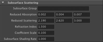
The following attributes are needed for subsurface scattering simulations. Note that the reduced absorption and reduced scattering coefficients and refraction index are usually obtained from specialized literature. The 3Delight User’s Manual contains a discussion about this topic and a reference to surface properties directly usable by 3Delight.
Subsurface Group
This attribute specifies a group name. Objects that have the same group name will belong to the same subsurface group. If the object that will undergo the subsurface simulation consists of several separate models, each of these models should be attached to a "Geometry Attribute Node" and this attribute should be assigned the same value in all of these nodes. Even if a model is closed and thus would be alone in its group, it is still required to specify a group name here. This attribute is empty by default. Leaving this attribute empty effectively turns off subsurface scattering.
Reduced Absorption
This attribute specifies the reduced absorption coefficients. Its default value is ‘0.002 0.004 0.007’.
Reduced Scattering
This attribute specified the reduced scattering coefficients. Its default value is ‘2.190 2.620 3.00’.
Refraction Index
This attribute specifies the refraction index of the simulated material. It is set to ‘1.5’ by default.
Coefficient Scale
The values for subsurface scattering use a millimeter scale. This attribute specifies the scale to apply these parameters when the objects are not exported in millimeters. The default value for this attribute is ‘0.1’, since 3Delight for Maya exports the objects in centimeters.
Subsurface Shading Rate
This attribute specifies the shading rate used for the subsurface simulation. Its default value is ‘1.0’.
MEL Scripts

The following attributes allow the user to call custom MEL scripts before and after the attached object’s geometry is output.
Pre Geo MEL Script
This attribute specify a MEL script that will be executed before the geometry is exported. More precisely, this script is called after all attributes of this "Geom- etry Attribute Node" are output and right before the geometry is instantiated. If this attribute is attached to several objects, it will be called once for each object. This attribute is empty by default.
Post Geo MEL Script
This attribute specify a MEL script that will be executed after the geometry is exported. More precisely, this script is called right after the geometry is instantiated. If this attribute is attached to several objects, it will be called once for each object. This attribute is empty by default.
The following table explains that variables that are automatically defined in the context of MEL scripts execution.
| Variable Name | Description |
|---|---|
| string $render_pass | This variable is assigned the currently rendered pass node name |
| string $shape_path | This variable is assigned the current object shape path.‘ |
string $attribs_node | This variable is assigned the current geometry attribute node name |
RIB Archive
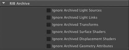
The following attributes allow the user to request that specific portions of an archive should be ignored. These attributes are meant to be attached to a "RIB archive node". For instance, they could be used to allow the same RIB archive to be used for a beauty pass (using the various Hypershade materials it contains) and in an occlusion pass, where the "Ignore Archived Surface Shaders" attribute would be turned on and an occlusion shader would be attached to the "RIB archive node". Refer to Section 3.11 [The RIB Archive Node], page 97.
Ignore Archived Light Sources
When this attribute is turned on, any light source in the archive will be disregarded.
Ignore Archived Light Links
When this attribute is on, the light linking information (illuminate statements) in the archive will not be considered.
Ignore Archived Transforms
Turning on this attribute will ignore any transforms stored in the archive.
Ignore Archived Surface Shaders
When this attribute is on, any surface shaders contained in the archive will be ignored.
Ignore Archived Displacement Shaders
Turning on this attribute will disregard all displacement shaders contained in the archive.
Ignore Archived Geometry Attributes
This attributes controls if the archived attributes that come from "geometry attribute nodes" are ignored or not. Note that attributes in the ‘Geometry’ sections of the "geometry attribute node", such as "Poly As Subd" will retain their effect regardless of this attribute.
User Attributes
Each Geometry Attribute Node can define as many arbitrary user attributes as needed. For each geometry attribute node, 3Delight for Maya will look for attributes whose name begin with "user ". This prefix is removed from the name and the attribute is output to RIB as a user attribute, along with its value. For instance, a ‘color float3’ attribute named ‘user_colorMultiplier’ will produce a Attribute "colorMultiplier". The supported attribute types are: string, bool, long, long2, long3, float, float2, float3 (color or non-color), double, double2, double3.