Overview
The Geometry Attribute Node is used to specify various parameters for a given object, such as the color, visibility, displacement, motion blur, lights to use to light the attached objects, and this includes RenderMan related attributes. Geometry attribute nodes are created and assigned inside the 3Delight Assignment Panel.
Geometry Attribute Node - Created empty
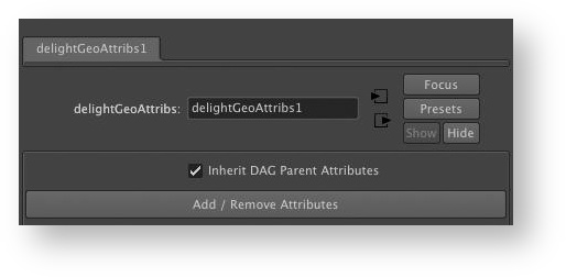
Geometry Attribute Nodes are created empty; it contains no attributes at all. It is an empty container where one can add just the relevant attributes. This avoids cluttering the UI and allows attribute inheritance. Attributes can be added and removed using Add / Remove Attributes button, which brings up The Add / Remove Attributes Window. Right-click on the Add / Remove Attributes button instead offers the same functionality through popup menus, which are more convenient when only one attribute or attribute group needs to be added or removed.Some of the attributes available in the Geometry Attribute Node clash with the Maya Render Stats attributes. The attributes defined in a Geometry Attribute Node attached to an object will override the related Maya Render Stats attributes. Refer to Maya Render Stats and 3Delight Attributes for more details.
Geometry Attributes
The following pages describe in details the purpose of all the attributes of the Geometry Attribute Node.
Scene Hierarchy Attribute Inheritance
It is possible to attach an attribute node to a transform node; its attributes will be inherited by all its children nodes. Attributes closer to an object have higher precedence (an attribute node can prevent inheriting its parent’s attributes if needed). As an example:
--waterfront <-------- RayTraceVisibilityAttrs
    |--rocks <-------- DisplacementAttrs
    |    |--rock1
    |    |--rock2
    |    |--rock3
    |
    |--trees
    |    |--tree1
    |    |--tree2 <--- InvisibleInReflectionsAttrs
Custom Hierarchy Attribute Inheritance
Sometimes the scene is structured in such a way that logical top-down attribute inheritance is not possible or complicated. For these particular cases one can create connections between attribute nodes, using the "alternate parent" plug, to define their hierarchical relationship. Attribute nodes connected this way have higher precedence than the scene parent’s attributes.Here is a variation of the previous sample scene:--BgdSet
|--rocks <-------- DisplacementAttrs <-------+
| |--rock1 |
| |--rock2 |
| |--rock3 |
| |
|--trees <-------- RayTraceVisibilityAttrs --+
| |-tree1
| |-tree2
|
|-flowers
|-grass
|-waterSurface
- Create the same geometry attribute nodes "RayTraceVisibilityAttrs", "DisplacementAttrs" as in the previous example.
- All objects under the "rocks" group still need their displacement attributes, so the "DisplacementAttrs" node is added to "rocks".
- It would be handy to have the trees and the rocks share the same raytracing attributes, so that one can turn the reflections on or off for everything using a single attribute. For the trees, it’s easy: attach the "RayTraceVisibilityAttrs" directly to the "trees" group.
- Now, the "rocks" groups already have the"DisplacementAttrs" node attached to them so it is impossible attach the "RayTtraceVisibilityAttrs" to that node. However, it is possible to define an alternate parent from which inherit attributes simply by creating a connection between the nodes’ ‘
altParent’ plugs.
‘altParent’ plugs, the direction of the connection is out from the parent, and in to the child. A given geometry attribute node can be the the parent of several other children geometry attribute nodes. It is generally best to use geometry attributes nodes that are not directly attached to a scene object as alternate parents. One way to create and edit them is through The 3Delight Relationship Editor.It is possible to mix both the scene inheritance and the ‘altParent’ connections inheri- tance. For instance, if a new "Shading Rate" attribute is created at the root of the scene, all objects under it – including "rocks" – would inherit it. Note that combining both ‘altParent’ and scene structure inheritance can potentially complicate things and make scene structure less maintainable. Inheritance Precedence List
The attribute nodes priority is as follows, starting with the higher priority attributes nodes:- If one is defined, the collection’s override attributes node.
- If there is an override attribute node defined and it has a geometry attributes node connected to its ‘
altParent’ plug, that later node is outputted; its ‘altParent’ plug is then checked for a connection to a geometry attributes node and if one is found, it is outputted, and so on. - If one is defined, the object’s collection attributes node.
- If the object has a collection attributes node defined and it has a geometry attributes node connected to its ‘altParent’ plug, that later node is outputted; its ‘altParent’ plug is then checked for a connection to a geometry attributes node and if one is found, it is outputted, and so on.
- If one is defined, the object’s attributes node.
- If the object has an attributes node defined and it has a geometry attributes node connected to its ‘
altParent’ plug, that later node is outputted; its ‘altParent’ plug is then checked for a connection to a geometry attributes node and if one is found, it is outputted, and so on. - If the object’s highest priority attribute (override, collection and object, in that order) has its ‘Inherit DAG Parent Attributes’ toggle set to off, the geometry attributes output process ends. If the toggle is on or if no ‘Inherit DAG Parent Attributes’ is found, the above six steps are repeated on the object’s immediate DAG parent.
