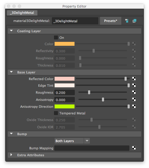
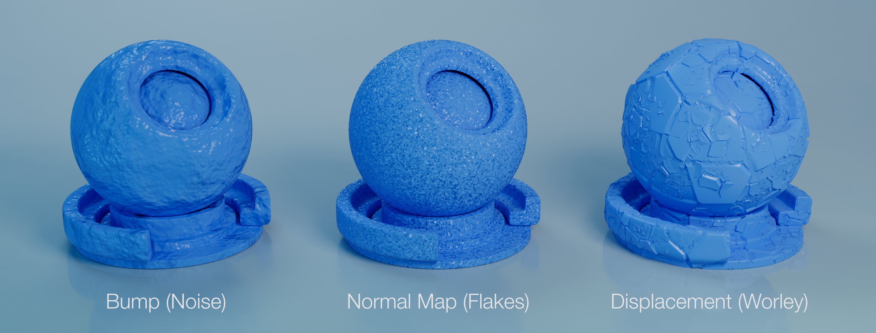
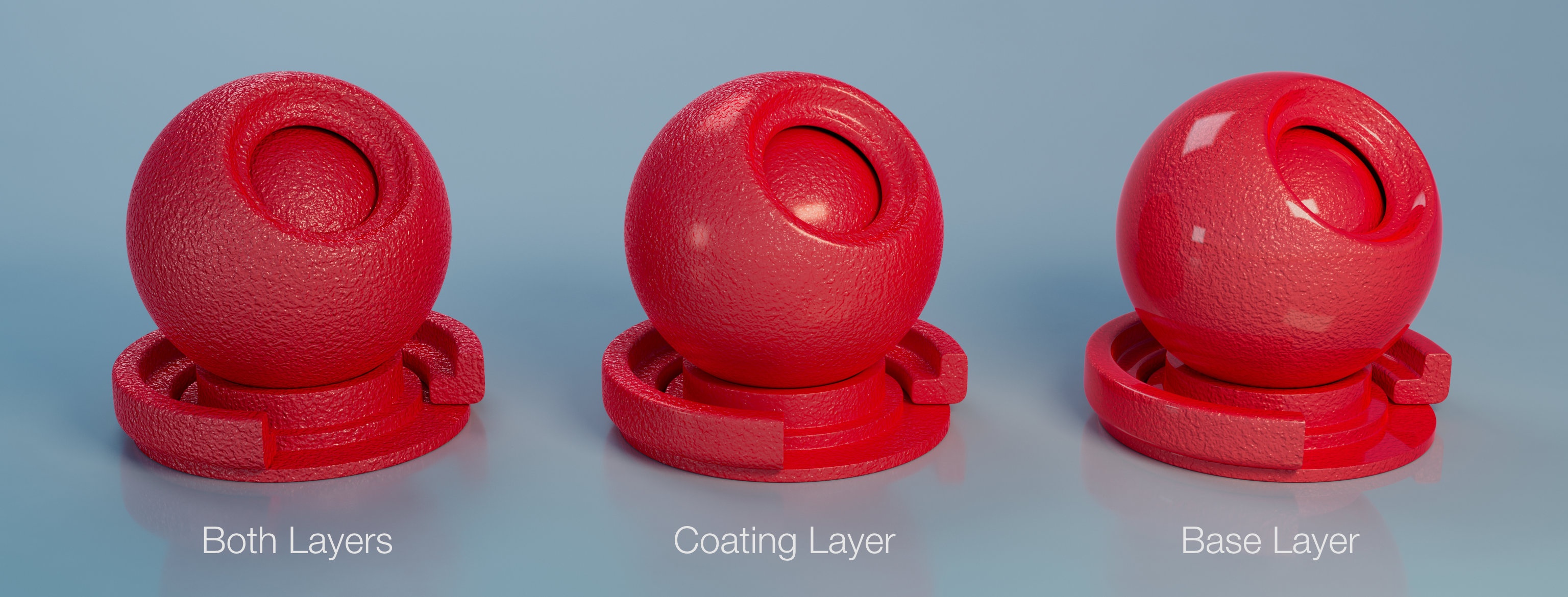
3Delight Metal with it's three main sections: Coating Layer, Base Layer and Bump.
Base layer allows for tempered (thin-film) metal simulation. The default values of the metal are these of copper.
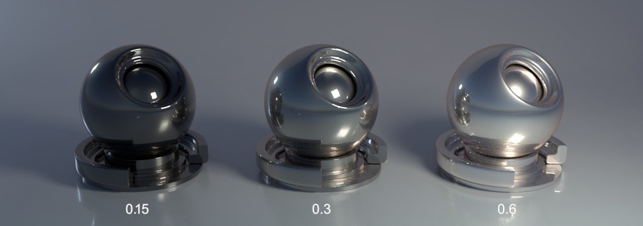
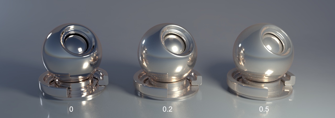
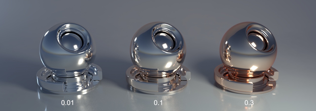
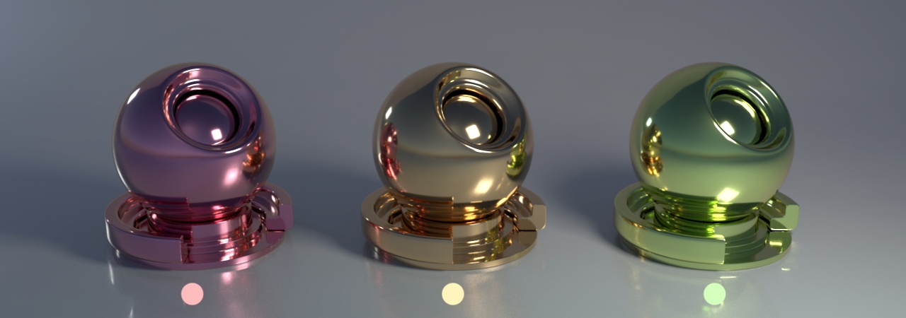
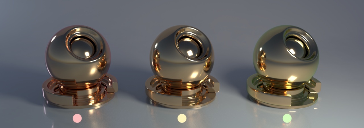
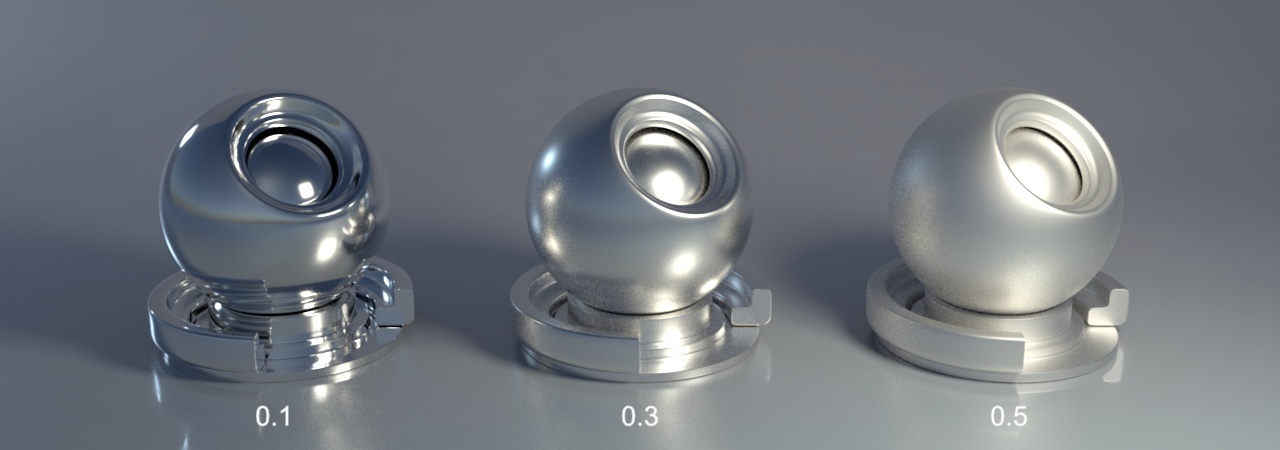
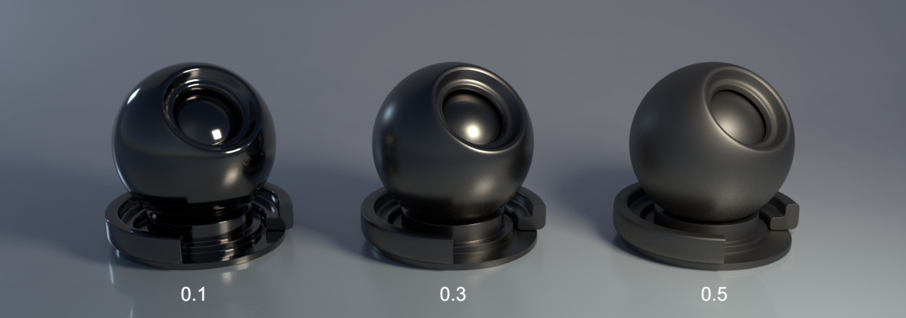
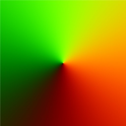
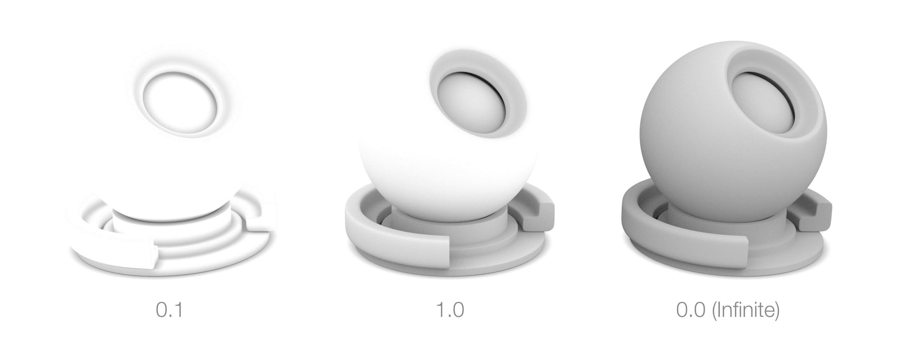
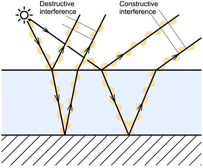
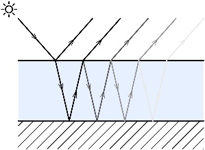
Specifies wether or not there is a coating on top of the Base layer. Visually, the presence of coating adds the following two characteristics to the look of the layer: Sets the colouring of the medium that makes up the coating. Light bouncing from the underlying metal will be tinted by this quantity. Thickness of the coating, described below, will affect how much transmittance color will be visible. Sets the ratio of light that bounces back when coming from a normal incident angle. For realistic coatings, this quantity should be kept low (only conductors have high reflectivity at normal incidence). Sets the roughness of the coating. Specifies the thickness of the coating. Thicker coatings will show more transmittance color. Spcifies the overall colour of the metal as seen from a straight angle. The following image shows a gold object (middle, color = [0.88, 0.60, 0.35] ) alongside two objects with the hue shifted. Describes how light is tinted at grazing angles. Sets metal roughness. The following two images show the effect on silver and on carbone. Anisotropy is an effect achieved by varying roughness independently in the U and V direction over the surface. A positive parameter value will increase U roughness and a negative value will increase V roughness. From left to right: -0.8, -0.4 and 0.4 . Sets the axis of the anisotropy on the surface. From left to right: [0.5, 1, 0], [1, 1, 0], [1, 0.5, 0] Each channel in the bitmap corresponds to a spatial dimension (X, Y and Z). These spatial dimensions are relative to a varying coordinate system based on the derivatives of position with respect to texture coordinates. Individual components for any direction should be in the range [–1, 1]. But to be encoded into an RGB texture with 8 bits per component, they are mapped into the range [0, 1]. So t XYZ (0, 0, –1) will be remapped to the RGB (0.5, 0.5, 0) values. It's also possible to use an angle texture to convert the direction to a color as show in the table below: The angle texture used for direction to color conversion The thickness of the oxide layer, in micrometers. Index of refraction of the oxide. Depends on the metal being rendered. Note that the Presets will automatically set this quantity to the correct value. Specifies the type of mapping desired – Bump Map, Normal Map or Displacement Map. In the case of a Normal Map, a color is expected in as a value, it can be encoded in the style or DirectX or OpenGL. In case of Bump Map or Displacement Map the shader will only consider the R value. Displacement maps can be interpreted as having their center value (the one that produces no effect) at 0.0 or 0.5. Displacement is performed in Object Space, so the scale of the geometry affects its intensity. For more intuitive results, a value of 1 for the object scale is recommended. The Displacement bound used is 1, so the ideal range of values is from 0 to 1. Above 1, displacement cracks might occur. Below 1 it might be inefficient. To achieve displacements bigger that 1, using the Intensity control is recommended. Value A colour input specifying bump direction (Normal Map) or intensity (Bump Map / Displacement Map). Intensity Specifies how intense is the the bump/normal/displacement mapping effect. A value of 0 means that geometry or normals will stay unchanged whereas a value of one will affect them fully. Layers Affected Select to apply bump/normal mapping to the Coating, Base Layer or Both Layers (default). Has no effect when Type is set to Displacement Map. Occlusion Distance Interference colours are produced when metal is heated and a thin film of metal's oxide forms on the surface. They are dependent on the wavelength and angle of the incident light, the thickness of the oxide film and the refractive indices of the oxide material. This effect is also called thin-film interference. Figure 1: Explanation of thin-film interference. When the phase difference between the two reflected beams is an even integer multiple of the wavelength of the beam in the film, then the two reflected beams tend to interfere constructively. If the phase difference between the two reflected beams is an odd integer multiple of the wavelength of light in the film, the beams interfere destructively. Figure 2: Light path in a thin film of the metal's oxide. Coating differs from tempering in that it is used to render a relatively thick medium that has been applied on top of the metal (such as is the case of car paint). Tempering produces a very thin layer of oxyde on the metal surface which can produces interference. From Wikipedia: "In the field of computer graphics, an anisotropic surface changes in appearance as it rotates about its geometric normal, as is the case with velvet". Anisotropy allows to set a different roughness depending on the orientation on surface. On real world surfaces, anisotropy is generated by microstructure characteristics of the surface. For example, brushed metal objects are polished in such way that there are a lot of parallel scratches on the surface. On CDs, the microstructure is produced by "tracks" describing the actual data. The following video shows the effect of anisotropy coupled with tempering.Coating Layer
On
Color
![]()
Reflectivity
Roughness
Thickness
Base Layer
Reflected Color
Edge Tint
Roughness
Anisotropy
Anisotropy Direction
Thin Film Layer
Thickness
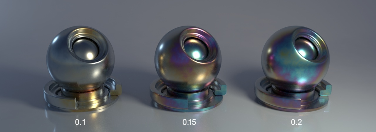
IOR
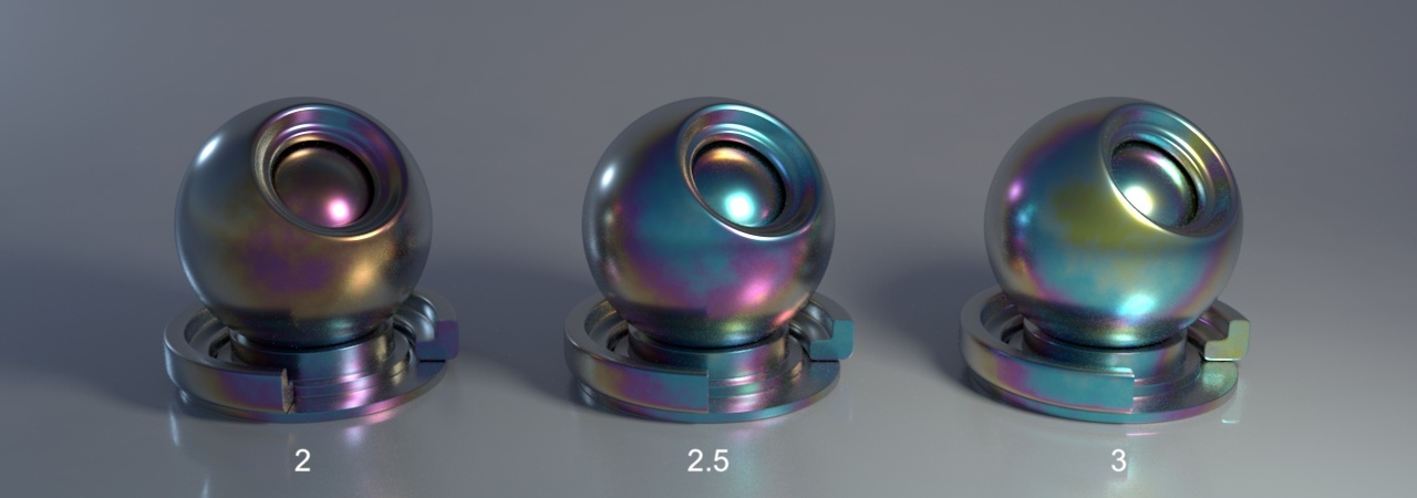
Bump / Normal / Displacement Map
Geometry
Technical Description
Tempering (thin-film interference)
Tempering vs. Coating
Anisotropy
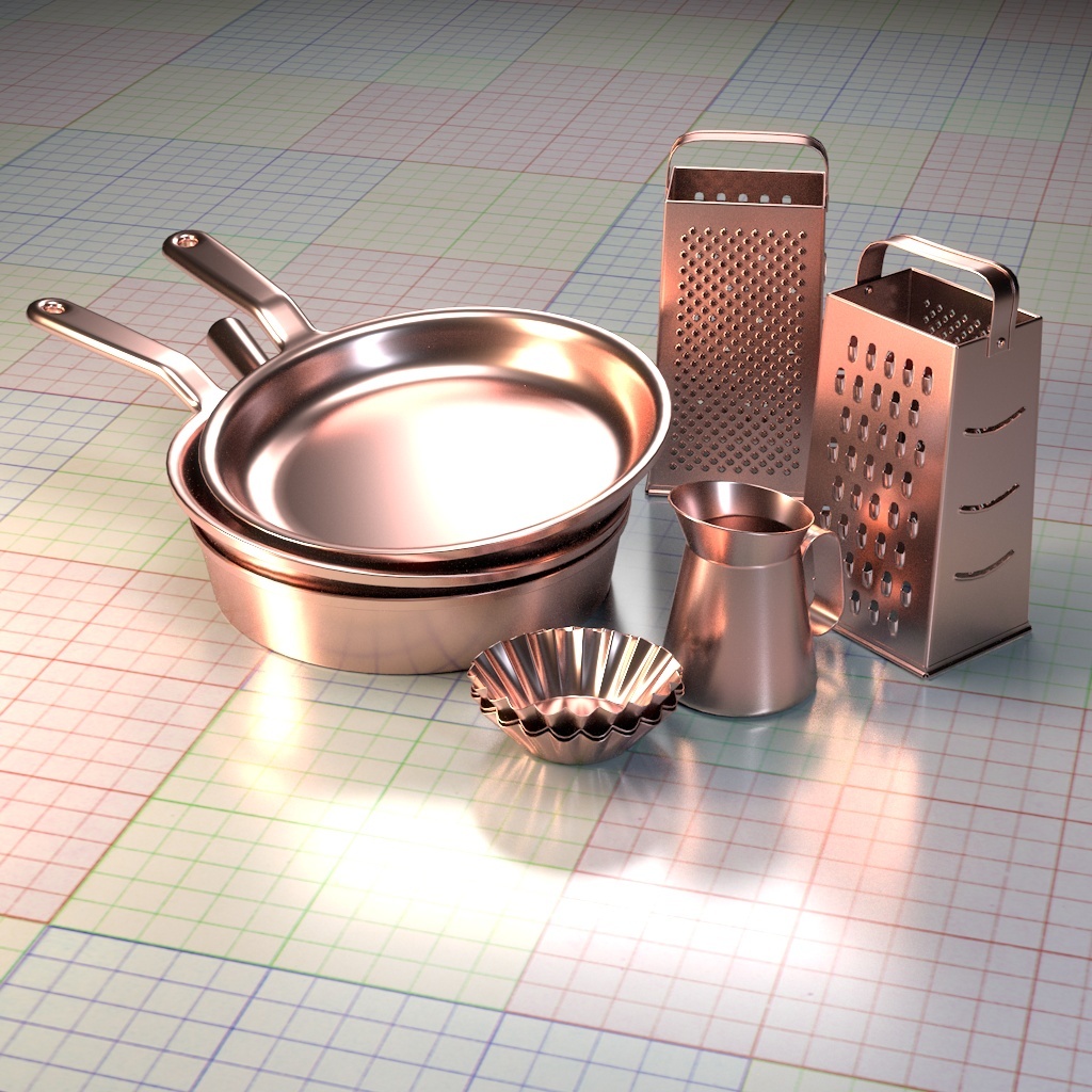
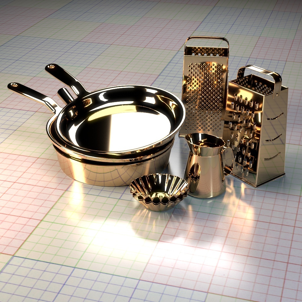
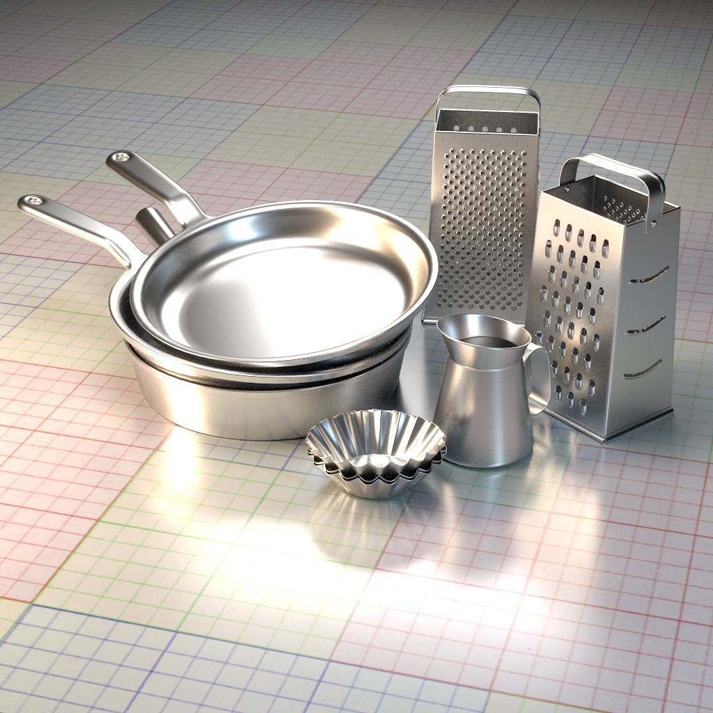
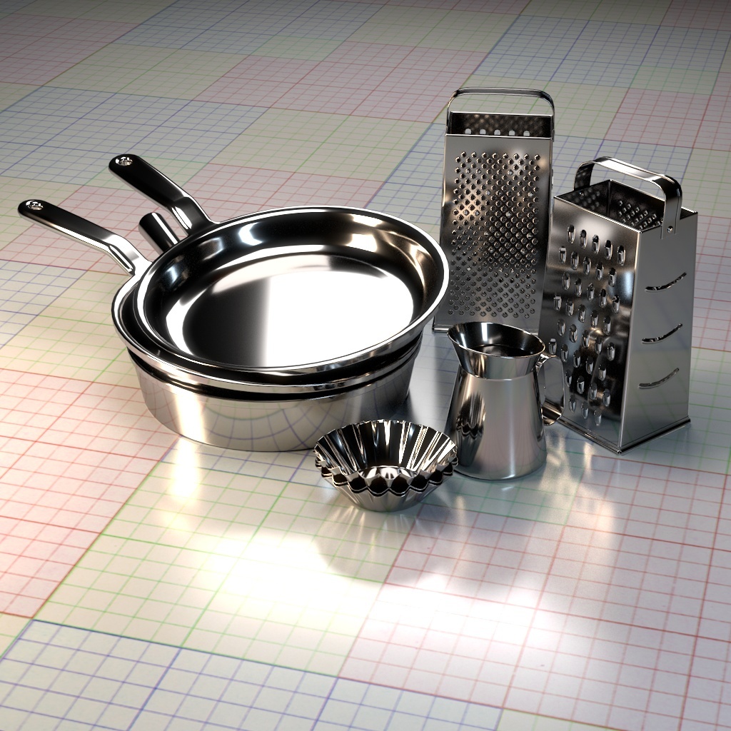
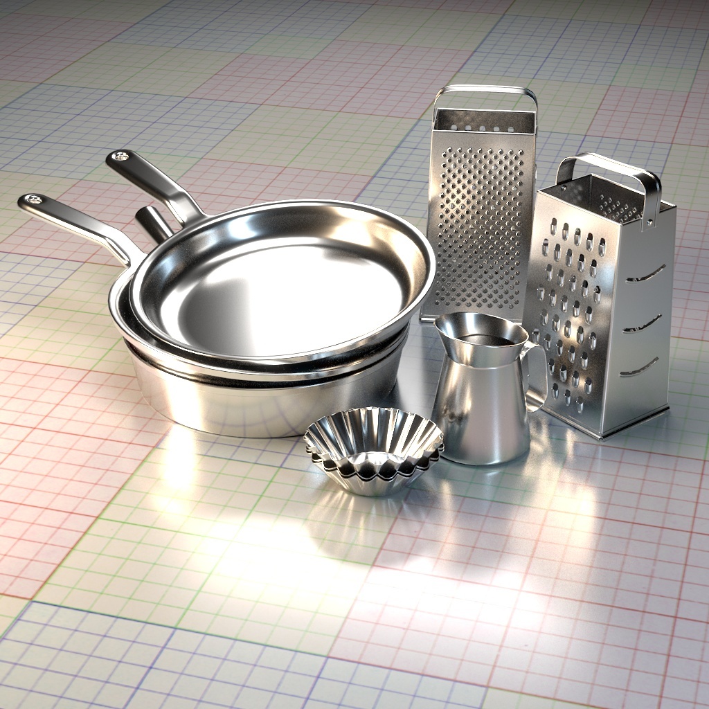
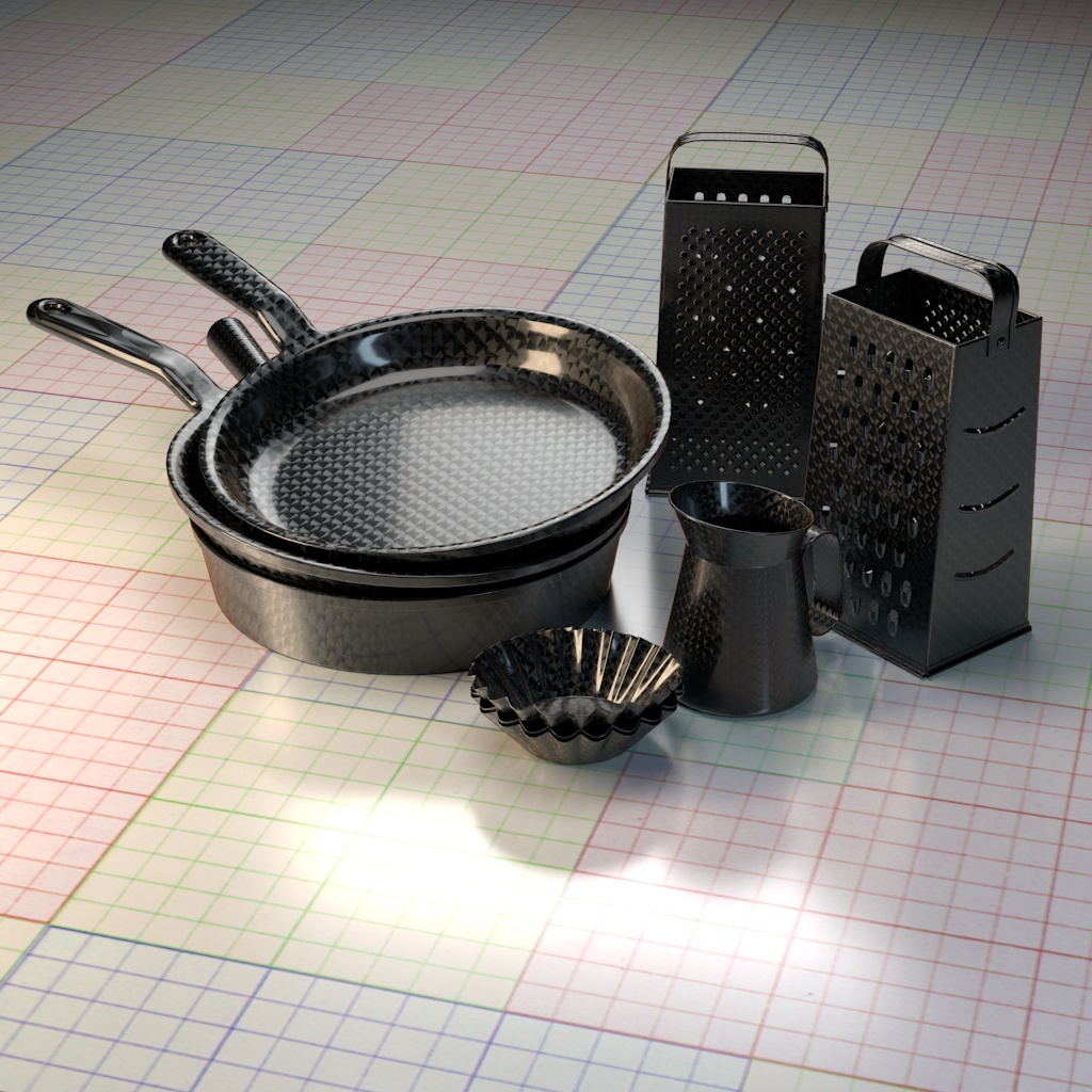
Included Presets
The following images show the presets available through the Attribute Editor.
CopperReflectivity [0.9466, 0.6, 0.5382]
| GoldReflectivity [ 0.8841, 0.6009, 0.3480]
|
AluminiumReflectivity [ 0.9094, 0.8889, 0.8715]
| IronReflectivity [ 0.5351, 0.5109, 0.4958]
|
SilverReflectivity [ 0.9521, 0.9246, 0.8911]
| CarbonReflectivity [ 0.1542, 0.1395, 0.1312]
|